Categories
Knowledge Support Support exacqVision Client Categories Products exacqVision Integrations

Using the Axis I8116-E Network Video Intercom with ExacqVision

This article applies to the Axis I8116-E Network Video Intercom using firmware 11.8.66.

ExacqVision does not currently support SIP calling functions. However, this device can be integrated for interactive operation with ExacqVision as detailed here.


In the example that follows we will step through an example scenario wherein pressing the door station call button brings the door station camera to the attention of the ExacqVision operator to trigger a door lock.

The following topics are discussed:

  • Wiring an electric door strike to the door station
  • Adding the device to ExacqVision
  • Enabling Two-Way Audio
  • Adding Associations
  • Creating custom Views
  • Creating an Event Monitoring profile

You will combine several features and functions within the ExacqVision Client. It is recommended that users acquaint themselves with the ExacqVision Client prior to use. We provide User Training Videos on these topics.<br><br>

Wire a Door Strike

The simplest configuration is that of a single electric door strike, or maglock, wired directly to the door controller.

The Axis I8116-E can be wired in a number of different ways, using PoE, external power sources, A9801 Relay, A9161 Network I/O Relay, or an Axis access control system. For more information on the many wiring and hardware configurations please refer to the manufacturer’s website or documentation. <br><br>

Add the Device

  1. You will want to use a web browser to log into the device and perform the initial setup, which at this state usually means setting a non-default username/password, and possibly setting a static IP address.<br><br>
  2. The call button should be enabled by default.

    <br><br>
  3. The device’s default settings create a ‘VMS’ entry under the Contact List menu. This ‘VMS’ contact will already be listed in the Recipients field. If you do not see this, enter it now.<br><br>
  4. If you do not already know the IP address of the door station, you will need to discover it on the network.<br>
    • If using the Find IP Cameras tab on the Add IP Cameras page, note that you may find the device listed twice. Ignore results with a 169.254.x.x address. You will ant to use the IP address in the same range as your ExacqVision VMS, however this result may be discovered with ‘Onvif’ displayed in the ‘Type’ column. Access the discovered IP address in your web browser to set the username and password.

      <br><br>
  5. Add the device manually by clicking the New button under the IP Camera List in the top half of the page. Select AXIS VAPIX from the Device Type Selector. Enter the IP address in the same range as your ExacqVision VMS, then enter the username and password credentials before clicking Apply to add the device. The device should display a ‘Connected’ status in the IP Camera List before continuing.
    <br><br>

Enable Two-Way Audio

  1. Expand the Add IP Cameras node from the navigation tree.<br><br>
  2. Select the Audio Inputs/Outputs node nested beneath the Add IP Cameras node.<br><br>
  3. The resulting list displayed will show each door station device listed twice. Note the column, titled Audio. One of these rows shows ‘Audio,’ while the other displays ‘Audio Output.’ For easier identification we can apply our own labels here. We change ‘Audio Output’ to ‘Talk’ and change ‘Audio’ to ‘Listen.’
    <br><br>
  4. Find the Record Enable column. Place a check in the box for both of these rows for the device. This enables two-way audio functions within ExacqVision<br><br>
  5. Press the Apply button to save your changes. Use the Talk and Listen buttons to verify audio is functioning and adjust the audio gain as desired in the door station’s web browser interface.<br><br>

IMPORTANT: Client workstations intended for use with two-way audio devices MUST have a microphone enabled. Two-way audio menus and controls are disabled or hidden until a microphone is recognized by the operating system. Each client workstation used for two-way audio must have its own microphone.<br><br>

Add Associations

You have the option of using soft triggers and audio controls from the top toolbar in live view, but these will open dialogues showing all system options. Controls that are used frequently and directly related to the specific camera being displayed in a panel may be easier for operators to use when added as Association buttons within the camera panel.

  1. Select the Associations node from the navigation tree.<br><br>
  2. The panel along the left lists existing cameras. Find and click to select the door station.<br><br>
  3. From the Available Controls panel, we select the ‘Listen’ option we relabeled earlier and click Add. There will be two controls labeled ‘Talk’ that we relabeled earlier. Select and add the one showing the microphone icon.<br><br>
  4. So that your ExacqVision operators can unlock the door remotely, find and add the control labeled ‘Door.’
    Note: This control may be relabeled from within the door station’s web browser interface, but is labeled ‘Door’ by default for us.<br><br>
  5. You should now have three Associated Controls listed. You may wish to edit the Button Style listed. ‘Sustained’ requires a click on, and another click to turn off. ‘Momentary’ functions only while a user is pressing down the button which will also prevent a user from accidentally forgetting to lock the door or leaving a microphone on. You may refer to the User Manual or Associations training video for more information on customizing your Associations.<br><br>
  6. Click Apply to save your changes when done.

<br><br>

Create Custom Views

In our example we will create a View to display when triggered, rather than changing a single video panel. Learn more about these two options in the Event Monitoring training video. To make this work, we will create two custom Views to use later when creating an Event Monitoring profile. Refer to the Views training video if you need more details on performing these steps.

  1. Select the Views node from the navigation tree.<br><br>
  2. Click the New View button, then enter a descriptive name. In this example, we name our view ‘East Entry.'<br><br>
  3. Select a layout for the view from the layout toolbar above. This view may have a single panel layout showing only the camera view from the door station, or you may use a multi-panel layout displaying the door station and other cameras showing the entry from different angles.<br><br>
  4. Use the Available Items panel to find your door station camera and drag it to the empty panel in the layout. If using a multi-panel layout, fill the other panels as you like. <br><br>
  5. Because the Associations are already displayed, an ExacqVision operator may easily enable/disable each when viewing in Live mode. However, if you’d like the Microphone or Speaker to be on automatically upon the view changing, you may also drag one of these onto the layout as well. Only one may be active.<br><br>
  6. Click Apply to save you changes when done.<br><br>
  7. Since we are changing the entire view displayed in Live mode, we will also want to create a view that is displayed when the door station is not in use. Repeat the steps above to create another view titled ‘Default View.’

<br><br>

Create an Event Monitoring Profile

Next you will create the Event Monitoring profile that changes the view displayed while in Live mode.

  1. Select the Event Monitoring node from the navigation tree.<br><br>
  2. Click the New button under the Profiles panel to begin creating a new profile.<br><br>
  3. Enter a descriptive Name under the Profile Configuration panel. Our example will name this ‘East Entry’ for the door where it is being placed.<br><br>
  4. The option you select for the Show Event List menu will depend on your intended use.
    • Never is the less obtrusive option as it hides the Event List from popping up in our view. The trade off for this is you will probably want to set Timeout later so the View changes back to the default display after a given amount of time. Without this, the displayed View will remain on the door station camera.
    • On Event will pop open the Event List window which some users do not like. However, the benefit of this is the ExacqVision user can decide when to return to the default View and the View will not change in the middle of being used simply because a timer ended. When the event is cleared the Event List window will disappear.
    • Always will always be displayed whether or not the door station is being utilized.<br><br>
  5. Checking the Show Newest Event box is optional. This feature is most useful when many possible events are included in an Event Monitoring profile. An example may be a site with multiple door stations, in which case checking this box will change the view to display the station with the most recently pressed Call Button.<br><br>
  6. As mentioned previously, this example will use ‘View’ from the Type field. Refer to the Event Monitoring training video for more on the ‘Video Panel’ option, which does not require creating custom Views.<br><br>
  7. Under Client Actions in the middle of the window is where you will create the actions that occur when triggered by various events. Our first row, currently labeled ‘Unknown’ should already be highlighted because we are creating a new profile.<br><br>
  8. From the Event Type panel list below, select ‘Default’.<br><br>
  9. From the Action Type panel list, select Switch View. Note that you could also opt to make your default display a Tour, which is covered in the Tours training video.<br><br>
  10. From the Action Target panel list, select the default View you created earlier.<br><br>
  11. Click the New button under the Client Actions panel in the middle of the window. This adds a new row to configure.<br><br>
  12. With the newly created row highlighted, select Input Trigger from the Event Type list.<br><br>
  13. The door station has already named the input for you. Locate the door station in the list. It has several inputs, select the one labeled ‘Call button’. Do not enable the ‘Lasts at Least’ checkbox.<br><br>
  14. From the Action Type list, select Switch View.<br><br>
  15. From the Action Target list, select the door station View you created earlier. In our example we named this ‘East Entry’.<br><br>
  16. Your next choice will depend on the option you selected from the Show Event List, in step 4, above.
    • If you chose Never and want the Live view to return to your default view after a set number of seconds, uncheck the Confirm box and set your Timeout as desired.
    • If you chose On Event or Always and want to allow your ExacqVision users to acknowledge the event to return to the default view, leave the Confirm box checked.<br><br>
  17. Click the Apply button to save your changes when done.

<br><br>

Handling Calls From ExacqVision

  1. Using the ExacqVision Client software, browse to Live mode.<br><br>
  2. By default, the panel along the left side of the window displays a list of Live Cameras. Using the options at the bottom select Views to update this panel to Live Views.<br><br>
  3. The Live navigation panel lists System Views, User Role Views, User Views, and System Tours, which includes any Views created earlier in the process of configuring our profile. Towards the bottom is a list of Event Monitors.
    <br><br>
  4. Find the name of the Event Monitoring profile you created. Again, our example was named ‘East Entry’. Drag this profile to the cameras panel to the right.<br><br>
  5. You should now be viewing your default View. When the Call Button on the door station is pressed the View will change to display the door station camera view you created earlier.<br><br>
  6. The Association icons we added earlier can be seen at the bottom corner. The door station will continue to ring until an ExacqVision user presses the Talk button or the configured ring timeout is reached.
    <br><br>
  7. Press the Talk button to transmit audio from your client workstation microphone to speak to door station users. Press the Listen button to hear door station users speaking.

    Note: Audio from Talk and Listen actions may be buffered, presenting a delay. Practice with the system to gain a feel for this on your network.<br><br>
  8. If you have correctly wired a door strike, maglock, or other electronic locking mechanism to the door station, pressing the icon for the output will unlock the door.

    Note: Door controls may be customized within the door station’s web browser interface.<br><br

Door Station Visitor Operation

  • A visitor using the door station may simply press the Call Button to activate the Event Monitoring profile, as created above.<br><br>
  • The use case detailed in this article does not prevent the door station from being used for SIP calls.

    Once a SIP server has been configured within the door station’s web browser interface, a SIP call may be initiated by pressing the Call Button.

    Note: When used together with SIP, any press of the Call Button will continue to trigger an Event Monitoring profile configured to do so.<br><br>

<br>

Categories
Cloudvue Cloudvue Cameras Knowledge Support Support Illustra Categories Products

Connecting an Analog Microphone to a Cloudvue C2C Camera

Cloudvue’s cloud-based recording solution provides the ability to record and playback audio. Many models of Illustra IQ cameras configured for Camera to Cloud (C2C) recording with Cloudvue’s services provide audio capabilities. Check your specific Illustra IQ camera model to determine audio support.

Considering audio quality, refer to manufacturer recommendations and guidelines on microphone selection and installation placement.

<br>

Camera Terminals

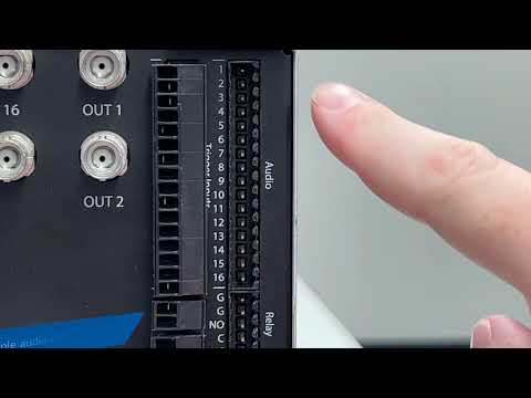
When examining your Illustra IQ camera, locate the I/O terminals. Determine which terminals are used for audio input. Examples from different models of Illustra IQ cameras are pictured below.

In this image, the icon with the triangle on the right is the positive terminal. The spaced lines on the left indicates ground.

<br><br>

Microphone Wiring

You will need a microphone with a pre-amplifier capable of producing a line level output that can be connected directly to the camera’s audio inputs.

If using a mic level output microphone, you will need a mic pre-amp to boost the audio to line level output for connection to the rear audio input terminals. Some microphones on the market have built-in pre-amps and others may require an external pre-amp.

There are many analog microphone options on the market. This article will focus on the Louroe Verifact A microphone used with an APR-1 single zone base station since it is a very commonly encountered device.

Looking at the back of a Louroe base station you will see that there are terminal inputs to connect your microphone to the base station and RCA style jacks for input and output.

The terminals on the microphone and base station are marked A, B, and C. Connect A on the mic to A on the base station, B to B, and C to C.

Since the audio output from the Louroe base station is an RCA jack and the camera does not have RCA audio inputs, you have two options. You may strip the wire end of a common RCA to RCA audio cable or purchase an RCA to bare wire cable. These may be found online and have already been striped and separated for you.

Connect the RCA connector to the audio output of the base station. With the bare end of the wire you’ll connect the conductor wire to the positive audio input terminal. In most cases this will be red. Connect the ground wire to the negative/ground audio input terminal, this will usually be black.

<br><br>

Preparing the Camera

Prior to changing the camera to Cloudvue Mode you will need to enable audio functions.

NOTE: Audio recording is restricted by law in many areas so this is disabled by default. Check the laws for audio monitoring and recording in your area prior to use since these can vary from video recording laws.

If your camera is already in Cloudvue Mode you will need to factory default it, then log into it as you would a standard IP camera using your web browser. Follow the camera manual’s steps for factory defaulting the device and accessing it within your web browser.

  1. Navigate to the Audio page, under the System menu.
  2. Check the box to Enable Audio.
  3. Select ‘External’ from the Input Source drop-down (only applicable on select models).
  4. Check that the Input Enable box is marked.
  5. Adjust the Input Volume level as needed.

After enabling audio, you will enable Cloudvue Mode.

  1. Navigate to the Maintenance page, under the System menu.
  2. Select the Cloudvue tab.
  3. Enter the Cloudvue Partner and Cloudvue Data Center as directed by your Cloudvue dealer before clicking the Apply button.

<br><br>

Cloudvue Audio Configuration

Follow the steps listed elsewhere for adding video devices to your Cloudvue account.

From your Cloudvue Settings page, select the Devices tab.

Beneath the C2C Settings section, click the Audio tab. This tab features a volume slider, which you may need to use to adjust for your installation. Note, the checkbox beside the Mute setting is disabled, stating it is in the ‘Off’ position. This is the default behavior and allows audio to be recorded. Checking the box, changing it to ‘On’, will mute all audio and nothing will be recorded or heard.

<br><br>

Audio Playback

The Archive search timeline in Cloudvue does not require that audio channels be selected and does not display audio on the timeline. When playing recorded video, the associated audio will automatically be played back with the corresponding video and is included with saved clips.

<br>

Categories
Knowledge Support Support exacqVision Client Categories Products exacqVision Integrations Uncategorized

Using the Axis A8207 Door Station with exacqVision

This article applies to the Axis A8207-VE and A8207-VE MkII Network Video Door Stations using firmware 11.5.64.

exacqVision does not currently support SIP calling functions. However, these door stations can be integrated for interactive operation with exacqVision as detailed here.


In the example that follows we will step through an example scenario wherein pressing the door station call button brings the door station camera to the attention of the exacqVision operator to trigger a door lock.

The following topics are discussed:

  • Wiring an electric door strike to the door station
  • Adding the device to exacqVision
  • Enabling Two-Way Audio
  • Adding Associations
  • Creating custom Views
  • Creating an Event Monitoring profile

You will combine several features and functions within the exacqVision Client. It is recommended that users acquaint themselves with the exacqVision Client prior to use. We provide User Training Videos on these topics.<br><br>

Wire a Door Strike

The simplest configuration is that of a single electric door strike, or maglock, wired directly to the door controller.

The Axis A8207-VE and A8207-VE MkII can be wired in a number of different ways, using PoE, external power sources, A9801 Relay, A9161 Network I/O Relay, or an Axis access control system. For more information on the many wiring and hardware configurations please refer to the manufacturer’s website or documentation. <br><br>

Add the Device

  1. You will want to use a web browser to log into the door station and perform the initial setup, which at this stage usually means setting a non-default username/password, and possibly setting a static IP address.<br><br>
  2. The call button should be enabled by default.
    <br><br>
  3. If you do not already know the IP address of the door station, you will need to discover it on the network.<br>
    • If using the Find IP Cameras tab on the Add IP Cameras page, note that you may find the device listed twice. Ignore results with a 169.254.x.x address. You will want to use the IP address in the same range as your exacqVision VMS, however this result may be discovered with ‘Onvif’ displayed in the ‘Type’ column. Access the discovered IP address in your web browser to set the username and password.
      <br><br>
  4. Add the device manually by clicking the New button under the IP Camera List in the top half of the page. Select AXIS VAPIX from the Device Type selector. Enter the IP address in the same range as your exacqVision VMS, then enter the username and password credentials before clicking Apply to add the device. The device should display a ‘Connected’ status in the IP Camera List before continuing.
    <br><br>

Enable Two-Way Audio

  1. Expand the Add IP Cameras node from the navigation tree.<br><br>
  2. Select the Audio Inputs/Outputs node nested beneath the Add IP Cameras node.<br><br>
  3. The resulting list displayed will show each door station device listed twice. Note the column, titled Audio. One of these rows shows ‘Audio,’ while the other displays ‘Audio Output.’ For easier identification we can apply our own labels here. We change ‘Audio Output’ to ‘Talk’ and change ‘Audio’ to ‘Listen.’
    <br><br>
  4. Find the Record Enable column. Place a check in the box for both of these rows for the door station. This enables two-way audio functions within exacqVision.<br><br>
  5. Press the Apply button to save your changes. Use the Talk and Listen buttons to verify audio is functioning and adjust the audio gain as desired in the door station’s web browser interface.<br><br>

IMPORTANT: Client workstations intended for use with two-way audio devices MUST have a microphone enabled. Two-way audio menus and controls are disabled or hidden until a microphone is recognized by the operating system. Each client workstation used for two-way audio must have its own microphone.<br><br>

Add Associations

You have the option of using soft triggers and audio controls from the top toolbar in live view, but these will open dialogues showing all system options. Controls that are used frequently and directly related to the specific camera being displayed in a panel may be easier for operators to use when added as Association buttons within the camera panel.

  1. Select the Associations node from the navigation tree.<br><br>
  2. The panel along the left lists existing cameras. Find and click to select the door station.<br><br>
  3. From the Available Controls panel, we select the ‘Listen’ option we relabeled earlier and click Add. There will be two controls labeled ‘Talk’ that we relabeled earlier. Select and add the one showing the microphone icon.<br><br>
  4. So that your exacqVision operators can unlock the door remotely, find and add the control labeled ‘Door.’
    Note: This control may be relabeled from within the door station’s web browser interface, but is labeled ‘Door’ by default for us.<br><br>
  5. You should now have three Associated Controls listed. You may wish to edit the Button Style listed. ‘Sustained’ requires a click on, and another click to turn off. ‘Momentary’ functions only while a user is pressing down the button which will also prevent a user from accidentally forgetting to lock the door or leaving a microphone on. You may refer to the User Manual or Associations training video for more information on customizing your Associations.<br><br>
  6. Click Apply to save your changes when done.

<br><br>

Create Custom Views

In our example we will create a View to display when triggered, rather than changing a single video panel. Learn more about these two options in the Event Monitoring training video. To make this work, we will create two custom Views to use later when creating an Event Monitoring profile. Refer to the Views training video if you need more details on performing these steps.

  1. Select the Views node from the navigation tree.<br><br>
  2. Click the New View button, then enter a descriptive name. In this example, we name our view ‘East Entry.'<br><br>
  3. Select a layout for the view from the layout toolbar above. This view may have a single panel layout showing only the camera view from the door station, or you may use a multi-panel layout displaying the door station and other cameras showing the entry from different angles.<br><br>
  4. Use the Available Items panel to find your door station camera and drag it to the empty panel in the layout. If using a multi-panel layout, fill the other panels as you like. <br><br>
  5. Because the Associations are already displayed, an exacqVision operator may easily enable/disable each when viewing in Live mode. However, if you’d like the Microphone or Speaker to be on automatically upon the view changing, you may also drag one of these onto the layout as well. Only one may be active.<br><br>
  6. Click Apply to save you changes when done.<br><br>
  7. Since we are changing the entire view displayed in Live mode, we will also want to create a view that is displayed when the door station is not in use. Repeat the steps above to create another view titled ‘Default View.’

<br><br>

Create an Event Monitoring Profile

Next you will create the Event Monitoring profile that changes the view displayed while in Live mode.

  1. Select the Event Monitoring node from the navigation tree.<br><br>
  2. Click the New button under the Profiles panel to begin creating a new profile.<br><br>
  3. Enter a descriptive Name under the Profile Configuration panel. Our example will name this ‘East Entry’ for the door where it is being placed.<br><br>
  4. The option you select for the Show Event List menu will depend on your intended use.
    • Never is the less obtrusive option as it hides the Event List from popping up in our view. The trade off for this is you will probably want to set Timeout later so the View changes back to the default display after a given amount of time. Without this, the displayed View will remain on the door station camera.
    • On Event will pop open the Event List window which some users do not like. However, the benefit of this is the exacqVision user can decide when to return to the default View and the View will not change in the middle of being used simply because a timer ended. When the event is cleared the Event List window will disappear.
    • Always will always be displayed whether or not the door station is being utilized.<br><br>
  5. Checking the Show Newest Event box is optional. This feature is most useful when many possible events are included in an Event Monitoring profile. An example may be a site with multiple door stations, in which case checking this box will change the view to display the station with the most recently pressed Call Button.<br><br>
  6. As mentioned previously, this example will use ‘View’ from the Type field. Refer to the Event Monitoring training video for more on the ‘Video Panel’ option, which does not require creating custom Views.<br><br>
  7. Under Client Actions in the middle of the window is where you will create the actions that occur when triggered by various events. Our first row, currently labeled ‘Unknown’ should already be highlighted because we are creating a new profile.<br><br>
  8. From the Event Type panel list below, select ‘Default’.<br><br>
  9. From the Action Type panel list, select Switch View. Note that you could also opt to make your default display a Tour, which is covered in the Tours training video.<br><br>
  10. From the Action Target panel list, select the default View you created earlier.<br><br>
  11. Click the New button under the Client Actions panel in the middle of the window. This adds a new row to configure.<br><br>
  12. With the newly created row highlighted, select Input Trigger from the Event Type list.<br><br>
  13. The door station has already named the input for you. Locate the door station in the list. It has several inputs, select the one labeled ‘Call button’. Do not enable the ‘Lasts at Least’ checkbox.<br><br>
  14. From the Action Type list, select Switch View.<br><br>
  15. From the Action Target list, select the door station View you created earlier. In our example we named this ‘East Entry’.<br><br>
  16. Your next choice will depend on the option you selected from the Show Event List, in step 4, above.
    • If you chose Never and want the Live view to return to your default view after a set number of seconds, uncheck the Confirm box and set your Timeout as desired.
    • If you chose On Event or Always and want to allow your exacqVision users to acknowledge the event to return to the default view, leave the Confirm box checked.<br><br>
  17. Click the Apply button to save your changes when done.

<br><br>

Handling Calls From exacqVision

  1. Using the exacqVision Client software, browse to Live mode.<br><br>
  2. By default, the panel along the left side of the window displays a list of Live Cameras. Using the options at the bottom select Views to update this panel to Live Views.<br><br>
  3. The Live navigation panel lists System Views, User Role Views, User Views, and System Tours, which includes any Views created earlier in the process of configuring our profile. Towards the bottom is a list of Event Monitors.
    <br><br>
  4. Find the name of the Event Monitoring profile you created. Again, our example was named ‘East Entry’. Drag this profile to the cameras panel to the right.<br><br>
  5. You should now be viewing your default View. When the Call Button on the door station is pressed the View will change to display the door station camera view you created earlier.<br><br>
  6. The Association icons we added earlier can be seen at the bottom corner. The door station will continue to ring until an exacqVision user presses the Talk button or the configured ring timeout is reached.
    <br><br>
  7. Press the Talk button to transmit audio from your client workstation microphone to speak to door station users. Press the Listen button to hear door station users speaking.

    Note: Audio from Talk and Listen actions may be buffered, presenting a delay. Practice with the system to gain a feel for this on your network.<br><br>
  8. If you have correctly wired a door strike, maglock, or other electronic locking mechanism to the door station, pressing the icon for the output will unlock the door.

    Note: Door controls may be customized within the door station’s web browser interface.<br><br>

Door Station Visitor Operation

  • A visitor using the door station may simply press the Call Button to activate the Event Monitoring profile, as created above.<br><br>
  • The use case detailed in this article does not prevent the door station from being used for SIP calls.

    Once a SIP server has been configured within the door station’s web browser interface, a SIP call is initiated by dialing a designated SIP extension number prior to pressing the Call Button.

    Note: When used together with SIP, any press of the Call Button will trigger the Event Monitoring profile regardless of whether it was used when dialing an extension number or not.<br><br>

<br>

Categories
Knowledge Support Video Library Configuration Highlighted Video Guides Support Installation Youtube Video Library Categories Products exacqVision Hardware exacqVision Integrations

Connecting a Louroe Base Station to an ExacqVision Hybrid NVR

A walk through, how-to video on connecting analog audio base stations from Louroe to ExacqVision Hybrid NVRs.<br><br>

See also: Line Level vs Mic Level Audio for more details on the differences in these audio signals from various devices.

<br>

Categories
Knowledge Support Support exacqVision Server Categories exacqVision Hardware Products

Line Level vs Mic Level Audio

About Audio Signals

Audio signals are not all the same. There are four different types of audio signals:

  • Microphone (Mic) level
  • Instrument level
  • Line level
  • Speaker level

This article will focus on the two forms commonly encountered around NVRs and surveillance equipment, Mic Level and Line level.

Mic level signals, those coming from a microphone, are the weakest. These signals are usually in the range of 0.001 to 0.01 volts. Devices in this range require a pre-amp to increase the signal to line level voltage.

Line level signals, from pre-amps, are stronger than mic level. These signals usually range from 0.3 to 1.2 volts. Consumer devices are on the lower end of that range, while professional devices tend to be on the higher end of the range.

Connecting a device sending mic level output to a line level input will leave you unable to hear anything. The voltage is too low for what the input requires. Likewise, if you connect a line level device to a mic level input the result is clipping and distorted sound that is too loud because it is providing too much voltage for the input. <br><br>

System Audio Connectors

The style of connector used does not necessarily tell you whether to expect line level or mic level signals.

The system board audio inputs on many ExacqVision systems include 3.5mm jacks for line level input and mic level input, as illustrated below. While the terminal inputs for Hybrid systems are line level only.

<br><br>

Audio Devices in ExacqVision Software

ExacqVision IP NVRs will only have audio inputs and outputs on the system board. These connections are found on the same panel as the network ports, monitor outputs, and USB ports on the rear of the server.

Within the ExacqVision Desktop Client software, in Configuration mode, you will find these inputs by expanding the Server name from the navigation tree along the left-hand side. Then expand Configure System and the System Audio node. Click on the Audio Inputs/Outputs node under System Audio to find these devices.

ExacqVision Hybrid NVRs have additional hardware for analog audio/video inputs. Video connections are made by BNC connectors. Audio connections are made via terminal inputs. Some legacy systems could still be encountered that used with wiring harnesses in which both video and audio were connected via BNC.

On these Hybrid systems audio inputs are found in two locations within the Client software. The system board inputs are found, as noted above. The additional analog input terminals will be found by expanding the analog board node on the navigation tree. Modern ExacqVision systems list this as tDVRxxxx. Expanding this board on the navigation tree and clicking the Audio Inputs/Outputs node beneath it reveals the analog audio input terminals.

<br>

Categories
Knowledge Support Support exacqVision Server Categories Products

How to set up an Association to Listen to a live view as well as Trigger a Light To notify Employees they are Being Actively Listened to

Description 

If any customer is wanting to set up an event to trip when selecting 2 associations on live view to trigger a light to alert employees they are being listened in on.

Product USBDIO Module:

Steps to Reproduce 

The task was to create a live view association as well as a trigger to turn on a light when a Manager is listening to the live video feed in the client.

  • Step 1 Once the USBDIO module is connected navigate to the Trigger Input section in the Client and name the device.
  • Step 2 Name the Output that will trigger the light to turn on.
  • Step 3 Set up the Association for both buttons to show on the live view of the camera.
    The first association to create was the listening option for the camera.

Then next association is for the Event linking to turn the light on. This will be found under the USBDio Module in the list under associations.

  • Step 4 Create The event linking for the soft trigger and the Trigger input to turn the light on.
  • First the Soft Trigger: First select the Event Type for Soft Trigger. Then Create a new Event Source and name it accordingly. Select an Action Type of output trigger. Then For the action target select the Output. In this example it was the name Alert Light since the Module’s output will turn the light on or off when the button is enabled in live view.

Next create the Event linking for the Input Trigger. For the Event Type select Input Trigger. Then select the Event Source from the usbdio module which is the Reception Light. Action Type would be the output Trigger and Action Target is the Alert Light.

Once that is done you should be able to go to the live view and select both the association buttons to trigger on. This will allow listening to the live view as well as turn on a light to alert employees they are being listened to. The output could be a speaker, a light, globe. It should be able to be used in any case as long as you select the proper output/inputs, associate them properly, and then create the event linking to trigger the event.

Categories
Video Library Configuration exacqVision Client Categories Products

Audio Inputs and Outputs

For those with a desire to listen to audio or utilize two-way audio to speak to those on site, follow along to learn about configuring your ExacqVision audio inputs and outputs, whether they are analog devices connected directly to your server or IP devices connected across your network.
Categories
Knowledge Support Support exacqVision Client exacqVision Server Categories Products

Audio Troubleshooting

Some cameras have audio inputs, which is not the same as having a built in microphone.

Sometimes you may also have to do a combination of tasks to get the audio to work correctly in Exacq.

External Microphones

  • Is audio scheduled to record
  • Is audio supported on the device?
  • Is audio enabled in the cameras Web GUI?
  • Are the Audio Inputs/Outputs enabled in the client?
  • Is the gain/sensitivity set either to high or low?
  • Is the stream profile setup correctly to allow Audio?
  • Is the recording format correct (JPEG, H.264, H.265)? *
  • Is the Codec supported (G.711, ACC)? *
  • Have you checked the exacqVision Server logs?
  • Has the cameras firmware version been tested? *
  • Do they need an Audio Bridge?
  • Is a powered microphone connected?
  • Is it connected to correct inputs?
  • Is the polarity correct?
  • Have you defaulted the device?

* Check the camera integration page

Categories
Knowledge Support Support exacqVision Server Categories Products

Using Axis Networked Speakers with exacqVision for Pre-Recorded Clips
Description

Axis networked speaker(s) are individually capable of having pre-recorded audio clips loaded onto them for playback. Audio effects such as door bells, barking dogs, event announcements, and more may be desired for a given site.

Models C1410 / C2005

Playback of audio files from the network speaker(s) cannot be triggered through exacqVision Client or Server.

Whether or not the networked IP speaker is added to the exacqVision server as a licensed device, an operator may trigger various audio clips for playback through the device’s web browser interface or by using a REST endpoint for the device.

The REST endpoint cannot be triggered via exacqVision webhooks.

exacqVision webhooks are currently only capable of issuing ‘POST’ requests, but Axis networked speakers require a ‘GET’ request, as well as authentication to the device.

As a result the current workarounds are suggested:

  1. Trigger playback using API commands through a web browser.
  2. Trigger playback using API commands in your CLI.
  3. Write your own intermediary HTTP listener that accepts ‘POST’ requests from exacqVision webhooks and issues it’s own ‘GET’ requests to your device.

The above suggestions are for advanced users and assistance via Exacq’s Support team is not provided.

Model C1310-E

The C1310-E Network Horn Speaker provides a workaround to native plugin audio playback or the use of webhooks, mentioned above. The following steps detail how to configure a Digital Output and trigger audio clip playback through exacqVision. This method has been tested with Axis firmware 11.4.63 using exacqVision Server and Client 23.03.

  1. Log into the web interface of the C1310-E. Expand the System menu, then select Events.
    System menu<br><br>
  2. From the Rules tab, select ‘Add a rule.’
    Add a rule option<br><br>
  3. Using the Add rule dialog pop-up, provide a descriptive name for the rule. In our example we wish to trigger the built-in ‘Ding Dong’ audio clip, so simply name it ‘Ding Dong.’
    Add rule dialog<br><br>
  4. Complete the rest of the dialog options as seen in the picture below. Select ‘Digital output is active’ from the Condition drop-down menu and select the ‘Use this condition as a trigger’ checkbox.

    From the Action section, select ‘Play audio clip,’ then choose your selected audio clip from the Clip drop-down menu. Optionally, make any changes to the Repeat or Volume fields. Click ‘Save’ when done.
    Add rule dialog filled out<br><br>
  5. Within your exacqVision Desktop Client, enter Configuration mode, then navigate to the Event Linking setup page by clicking the Event Linking node from the tree on the left. <br><br>
  6. Along the bottom of the page, click the New button to create a new Event Linkage.
    Event Linking New button<br><br>
  7. In this example we will choose to create a Soft Trigger to manually trigger the audio playback, but you can just as easily choose another option to trigger playback. Refer to our User Training Videos for more on configuring Event Linking.

    From the Event Type menu, we select ‘Soft Trigger’, then click New under Event Source to create and name a new Soft Trigger.
    <br><br>
  8. Next, select the newly created Soft Trigger from the Event Source list.
    Event Source List<br><br>
  9. Select ‘Output Trigger’ from the Action Type list. You will not have the option of renaming the trigger from the device, but you will note that the C1310-E shows an Output 1 listed as a possible Action Target. Select this option as your Action Target.
    Action target selection<br><br>
  10. Click ‘Apply’ from the bottom of the page to save your changes.
    <br><br>
  11. Returning to Live mode in the client, click the ‘Soft Trigger’ menu icon from the toolbar above.
    Soft Trigger icon<br><br>
  12. From the Soft Trigger menu, you may trigger the audio playback by toggling your newly created soft trigger into Alarm state.
    Soft Trigger menu<br><br>

NOTE: The Axis firmware currently only allows one output trigger to be created at a time, therefore it is only possible to choose one audio clip for playback. Although, you may create many different Event Links to trigger the audio clip to play regardless of the source event it will play the same clip. See workaround methods above for the C1410 and C2005 if this presents an issue.

<br>

Categories
Knowledge Support Support exacqVision Server Categories Products

Audio from motherboard sounds “choppy”

Description

Users report “choppy” audio from motherboard audio outputs on Linux-based systems.

<br>

Affected platforms

exacqVision Server 5.8 to 7.2.3, on Linux systems

<br>

Symptom

Sound quality of audio coming from motherboard sounds “choppy”.

<br>

Workaround

No workaround

<br>

Resolution

Update to exacqVision Server 7.4.0.89244 or higher