Categories
Video Library Documentation Quick Start Guides Installation Highlighted Video Guides Youtube Video Library Categories Products exacqVision Hardware

exacqVision Q-Series Quick Start Video

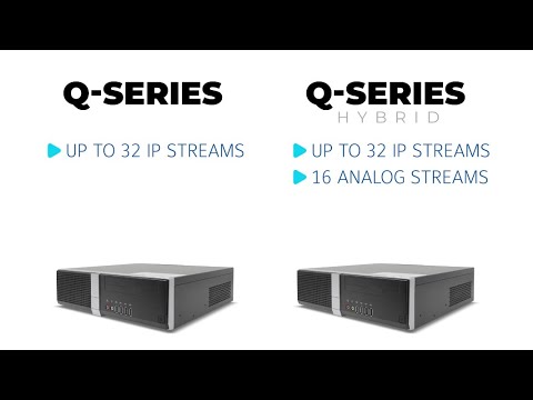
The exacqVision Q-Series brings together an optimal combination of performance and affordability into a single network video recording solution available in hybrid or standard models. This video will introduce you to the hardware and walk through initial setup.<br><br> Chapters<br> 00:00 Intro<br> 00:19 Unboxing<br> 00:38 Specs<br> 01:49 Setup<br> 03:16 Licensing<br>
Categories
Knowledge Support Support Categories Products exacqVision Hardware

Replacing a Hard Drive on Q-Series 2024 Refresh

  1. Looking at the rear of the system, remove the three screws indicated in the illustration below.
  1. Looking at the rear end of the top cover, remove the two screws indicated below.
  1. Slide the top cover towards the rear and pull off to remove it from the chassis.
  2. Remove the three screws indicated below.
  1. Remove the front bezel by lightly lifting the tabs indicated and rotating the top of the bezel away from the chassis.
  1. With the front bezel removed, looking at the front of the system, remove the two screws in the upper corners as indicated in the image below.
  1. Lift the drive plate to separate it from the chassis. Remove the hard drive retaining screws shown in the image below, supporting the drive from underneath.
  1. Detach the SATA power and data cables from the hard drive and attach to the replacement drive. Reverse the steps above to reassemble the system.
  1. When reattaching the drive plate, fit the three tabs on the front of the plate into the slots as shown.

<br>

Categories
Sales Materials Storage Calculator Documentation Categories Products exacqVision Hardware

How exacqVision Performance is Benchmarked

For help selecting the correct exacqVision Server hardware, please refer to our Configuration Calculator.

Exacq system performance is benchmarked under typical real-world conditions to provide meaningful context in selecting a system that meets the needs of your application. All performance guidelines are approximate, and we recommend having at least 20% extra data rate capacity for your installation. The following definitions and guidelines are used by our Configuration Calculator and should be kept in mind when configuring any system.

IP Stream

An IP stream is a video or audio connection transmitted over the network to the server. Many cameras are capable of providing more than one stream simultaneously.

Maximum IP Streams

The highest number of IP Streams the system is capable of recording. This is an upper limit on the number of streams that can be handled and may not be reachable based on the total amount of data from connected devices. Secondary streams from the same camera are included in this number. Datasheets for each system may be found on the Product pages of Exacq.com.

Video Throughput

The maximum amount of data that can be recorded while simultaneously performing reads for video search. Testing is performed so that users performing forensic searches should not expect significant delays in retrieving results while being able to record without interruption. Datasheets for each system may be found on the Product pages of Exacq.com.

The Maximum Throughput may be lower than the theoretical maximum disk throughput values reported by other’s systems but allows us to provide the expectation that users may perform functional searches in a reasonable time, whereas citing a higher write throughput to the disk would negatively impact a user performing searches in a real-world use case. Throughput values are also tested to ensure that storage drives, which are 100% full, are capable of removing old video files without negatively affecting the ability to write new files.

Our Configuration Calculator considers both Maximum IP Streams as well as the data throughput when recommending system hardware. Whichever limit is reached first is considered the cutoff before suggesting adding another system to the overall configuration.

While typically used to select an appropriate size and number of servers for new purchase, the Configuration Calculator may be a useful tool for existing systems when trying to determine if additional cameras may be added.

NOTE: X-Series systems manufactured through our partnership with Dell will list an increase in the number of streams over the prior generation Z-Series despite slightly lower disk throughput values. This is due to the higher prioritization the RAID management these systems place on writing data to disk versus read activity.

Network Interface

Tests are performed using default interface settings. With regards to the disk throughput, the network interface is a determining factor, e.g.- a disk that can write 3 Gbps will be limited to only 2.5 Gbps if that is the maximum throughput of the data crossing the network interface to be written to disk.

Active Search

When considering the ability to perform reasonable forensic searches, tests are performed to ensure that 2 hours of video from 4 simultaneous streams are returned within 2 minutes.

Operating System

Exacq systems are available with Windows or Ubuntu Linux operating systems. Each operating system is tested independently due to Linux ext4 file system’s ability to provide higher throughput in many server configurations than the Windows NTFS file system. Ext4 is capable of handling larger ranges of contiguous blocks of data, allowing it to work more efficiently with large files, reducing drive fragmentation, and has shown more efficient journaling and checksum processes.

Display Rate

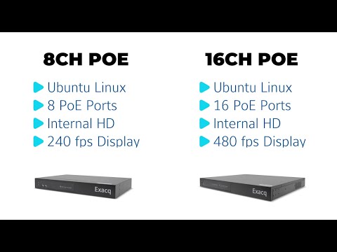
The local client’s display frame rate represents a client running directly on the chosen system, rather than a networked client workstation, to decompress and display live or recorded video. This is tested using 1080p H.264 video streams with default quality settings. H.264 requires significantly more CPU power to decompress than MJPEG or MPEG; thus, performance is the same or better using MJPEG or MPEG compression. Testing determines the total frames capable of being displayed without any additional applications running.

<br>

Categories
Quick Start Guides Documentation Categories exacqVision Hardware Products

Installing X-Series ReadyRails on Racks with Threaded Round Holes

The ReadyRails that ship with exacqVision X-Series NVRs are designed to be toolless when used with server racks that have square or unthreaded round mounting holes on the rack uprights. The following guide describes how to adapt these rails, using tools, for use with rack uprights with threaded round screw holes.

  1. Examine the each end of the rail and take note of the pegs, as indicated in the illustration below.
  1. Insert a flathead screwdriver into the slot at the end of each peg and turn to remove the pegs. Repeat this on the opposite end of the rail.
  1. Remove the end plate. Repeat this at the opposite end of the rail.
  1. Fit the L-bracket on the end of the rail around the upright, facing outward. Use installer provided screws to secure the rail to the rack’s upright. Use the bottom of the bracket for front/rear alignment as the bracket holes are in different positions on the front and rear of the rail.

<br>

Categories
Video Library Quick Start Guides Installation Highlighted Video Guides Youtube Video Library Categories exacqVision Hardware

exacqVision C-Series Quick Start Video

The latest C-Series systems from exacqVision provide ready-to-go live-monitoring stations for your exacqVision users, without the need to design your own systems or check specifications to display multiple video streams. These systems are built to achieve specific decoding and frame rates to meet the needs of video security users.<br><br> Chapters<br> 00:00 Intro<br> 00:27 Unboxing<br> 01:21 Model Comparison<br> 02:26 Port Identification<br> 03:26 Setup<br> 03:42 VESA Mount<br> 04:47 First Startup<br>
Categories
User Guides Documentation Categories exacqVision Hardware Products

X-Series Indicator Reference

Power Supply Indicators

LED IndicatorDescription
Green (Solid)A valid power source is connected to the PSU and the PSU is operational.
Amber (Blinking)Indicates an issue with the PSU.
Not LitPower is not connected to the PSU.
Green (Blinking)PSU firmware is being updated.

WARNING: Do not disconnect power or unplug the PSU while firmware is updating. Interruption of this process could lead to PSUs ceasing to function.
Green (Blinking and powers off)When hot-plugging a PSU, it will blink 5 times at a rate of 4Hz then power off. This indicates a mismatch due to efficiency, features, health status, or supported voltage.

WARNING: If two PSUs are installed, both PSUs must have the same type of label. Mixing PSUs is not supported, even if they have the same power rating.

WARNING: If two identical PSUs receive different input voltages, this can cause different output wattage and trigger a mismatch.

CORRECTION: When correcting a PSU mismatch, remove all power from the system then replace the PSU with the blinking indicator.

<br>

System Health and ID Indicators

The left control panel on the front of the system acts a button and provides an LED indicator. System ID mode, activated by pressing the control panel on the front of the system, or the ID button on the rear of the system will flash these LEDs to make identification in a server rack, from either side, easier.

LED IndicatorDescription
Blue (Solid)The system is powered on, healthy, and system ID mode is not active. Press the system ID button to switch to system ID mode.
Blue (Blinking)System ID mode is active. Press the system ID button to switch to system health mode.
Amber (Solid)The system is in fail-safe mode and should be inspected for issues or troubleshooting.
Amber (Blinking)The system is experiencing a fault. Check the System Event Log for error messages.
Look up specific error codes using Quick Resource Locator.

<br>

Drive Indicators

The LEDs on the drive carrier indicate the state of each drive. Each drive carrier has two LEDs: an activity LED (green) and a status LED (bicolor green/amber). The activity LED blinks whenever the drive is accessed.

  1. Drive status LED indicator
  2. Drive activity LED indicator
  3. Drive capacity label
LED IndicatorDescription
Green (Solid)Indicates the drive is online.
Green (Blinks twice per second)Indicates the drive is being identified, or preparing for removal.
OffIndicates the drive is ready for removal.

NOTE: Drive status indicator remains off until all drives are initialized after the system is powered on. Drives are not ready for removal during this period.
Green/Amber (Blinks green, ambers, then powers off)Indicates that there is an unexpected drive failure.
Amber (Blinking 4 times per second)Indicates the drive has failed.
Green (Blinking slowly)Indicates the drive is rebuilding.
Green/Amber (Blinks green 3 seconds, amber 3 seconds, then powers off after 6 seconds)Indicates that the rebuild has stopped.

<br>

iDRAC Direct (micro USB) Indicators

LED IndicatorDescription
Solid green for 2 secondsLaptop or tablet is connected.
Blinking green (on for 2 seconds, off for 2 seconds)Laptop or tablet connected is recognized.
LED offLaptop or tablet is unplugged.

<br>

Categories
User Guides Documentation Integrations Categories exacqVision Hardware Products

Using iDRAC on X-Series NVRs

What is iDRAC?

Integrated Dell Remote Access Controller (iDRAC) is a proprietary technology that allows IT administrators to remotely manage and monitor Dell-built servers. This includes software and hardware components.

The Exacq X-Series NVRs include iDRAC micro ports on the front of the system and iDRAC network interfaces on the back. The location of these is noted on the X-Series Quick Start Guide.

<br>

Out of the Box

iDRAC ports are not enabled out of the box. To enable either, or both interfaces, you must access the Lifecycle Control Center on the system.

Enabling iDRAC Ports

  1. During boot up of the system, watch for the boot options to appear on screen.<br><br>
  2. When shown, press the F10 key to boot into the Lifecycle Control Center.
    <br><br>
  3. The Lifecycle Controller automatically begins a network configuration wizard if it has not been configured before. You may select the Back button to exit the wizard.<br><br>
  4. From the Lifecycle Controller Home screen, navigate to System Setup &gt; Advanced Hardware Configuration.
    <br><br>
  5. Select iDRAC Settings.

    Continue to Step 6 to enable iDRAC Direct on the iDRAC micro port. Skip to Step 7 to enable iDRAC networking.<br><br>
  6. To enable the iDRAC micro port, select Media and USB Port Settings.
    <br>
    • Beneath USB Management Port, locate the iDRAC Direct: USB Configuration XML setting.
    • The default setting is ‘Enabled while server has default credential settings only.’ However, for the security of your system, these credentials are changed before shipping from the factory.
    • Change the above-mentioned setting to ‘Enabled‘.
    • Select the Back button.<br><br>
  7. To enable the iDRAC network port on the rear of the system, select Network.


    NOTE: A VLAN is recommended as a best security practice when iDRAC is in Dedicated or Shared LOM mode, to isolate network access to iDRAC’s management interfaces. Technologies such as VLANs and firewalls help ensure that only authorized users can access network resources.<br><br>
    • Beneath Network Settings, change the Enabled NIC setting to ‘Enabled‘.
    • Leave the NIC Selection set to ‘Dedicated‘.
    • Scroll down to the IPv4 Settings section. The default settings are as follows:
      • Enable IPv4: Enabled
      • Enable DHCP: Enabled
      • Static IP Address: 0.0.0.0
      • Static Gateway: 0.0.0.0
      • Static Subnet Mask: 0.0.0.0
      • Use DHCP to obtain DNS server addresses: Disabled
      • Static Preferred DNS Server: 0.0.0.0
    • If you plan to connect this interface to a network with a DHCP server, you may leave the settings as they are.
    • If you wish to use a static IP address for the iDRAC interface, change the Enable DHCP setting to ‘Disabled‘ and enter the proper Static IP address settings in the fields below.
    • Select the Back button when done.
  8. Press the Finish button to save your changes and return to the System Setup menu.<br><br>
  9. Press Finish again to return to the Lifecycle Controller main menu.<br><br>
  10. Leave the Lifecycle Control Center and boot to the operating system by selecting the Exit option in the corner of the screen.

<br>

Accessing the iDRAC9 Dashboard

The iDRAC9 Dashboard is accessible using any modern web browser, but there are various methods available to reach it: Local, Network, and USB (iDRAC Direct).
<br>

Local Browser Access

Accessing the iDRAC9 Dashboard locally requires a keyboard, mouse, and monitor connected to the system.

  1. Log into the system’s operating system (Windows or Linux).<br><br>
  2. Open a web browser.<br><br>
  3. In the browser address bar, enter: https://169.254.1.1<br><br>
  4. Use the browser’s advanced settings to continue past the warning message. This message appears because the SSL certificate is self-signed.<br><br>
  5. Log into iDRAC using the proper credentials.

<br>

Network Access

iDRAC network interfaces support RJ45 jacks, with 1G BASE-T Ethernet Cat5/6 cables.

The Lifecycle Control Center provides the ability to set the iDRAC network interface to DHCP or static IP address.

If set to a static IP address, a site administrator should be able to provide the configured address.

If configured for DHCP, but a DHCP server is not available, or has no available addresses to offer, this interface should fall back to 192.168.0.120. Otherwise, you may need to determine what address the DHCP server assigned to the system.

Whether using a static or dynamically allocated IP address, you will enter this address into the browser’s address bar.

Example: https://172.10.10.4

<br>

USB Access (iDRAC Direct)

iDRAC Direct allows you to utilize the front-facing iDRAC micro port to connect directly to the system over USB, say from a laptop, which makes ad hoc management in a server room/stack easily accessible.

iDRAC micro ports couple with a USB 2.0 Micro-A or Micro-B connector. You will need a cable with either of these interfaces to connect between the X-Series system and your laptop/workstation. Cable length should not exceed 3ft (0.91m). Cable quality could affect performance. The iDRAC micro port is a Micro-A type port, which will accept either Micro-A or Micro-B connectors, but will not accept USB 3.0/SS Micro-B.

  1. Before beginning, you MUST disable all other network or wireless interfaces on the laptop/workstation you wish to connect from.<br><br>
  2. Make sure the iDRAC micro port is enabled, see Step 6 of Enabling iDRAC Ports above.<br><br>
  3. Turn the flat side of the USB micro connector to the right, so that the beveled side of the USB micro connector faces left, then insert the connector into the iDRAC micro port.<br><br>
  4. Wait a few moments and the laptop/workstation should detect a new virtual network interface.<br>
    This can be seen using the ipconfig command on Windows, or ifconfig command on Ubuntu/Linux.<br>
    The IP assigned to this interface should be 169.254.0.4.<br><br>
  5. Open a web browser on the laptop/workstation. In the browser address bar, enter the IP of the iDRAC micro port: https://169.254.0.3<br><br>
  6. Log into the iDRAC Dashboard with the proper credentials.

<br>

Logging into the iDRAC9 Dashboard

When logging into the iDRAC9 Dashboard, use the following credentials

Username: root

Password: admin256

Consider changing your iDRAC Dashboard password using the steps below.

<br>

Changing the iDRAC credentials

Most system users will probably only use the default root user account and factory set password. However, up to 16 local users may be configured in iDRAC with specific access permissions.

If you are already connected to the iDRAC9 Dashboard, you may do this using the following steps:

  1. Select the iDRAC Settings menu.<br><br>
  2. Select Users from the menu drop-down, or from the tabs on the iDRAC Settings page.

    <br><br>
  3. Select Local Users.
    <br><br>
  4. Edit an existing account or add a new user account.

If you are not connected to the iDRAC9 Dashboard, you will need physical access to the system.

  1. During boot up of the system, watch for the boot options to appear on screen.<br><br>
  2. When shown, press the F10 key to boot into the Lifecycle Control Center.
    <br><br>
  3. The Lifecycle Control Center automatically begins a network configuration wizard if it has not been configured before. You may select the Back button to exit the wizard.<br><br>
  4. From the Lifecycle Controller Home screen, navigate to System Setup &gt; Advanced Hardware Configuration.
    <br><br>
  5. Select iDRAC Settings.
    <br><br>
  6. Scroll down to find and select User Configuration.
    <br><br>
  7. Select the text field beside Change Password to enter a new password.
    <br><br>
  8. When done, select the Back button.<br><br>
  9. Click the Finish button to save your changes.

<br>

iDRAC9 Dashboard Basics

The iDRAC9 Dashboard provides a quick overview of the system. Describing all aspects and controls is outside the scope of this document. The items you should pay the most attention to are your system and drive health.

The Dashboard home page shows a high-level overview of System Health and Drive Health.

Clicking on Details for either of these will bring you to the corresponding pages. You may also reach these pages by selecting System or Storage from the top menu bar.

The System &gt; Overview page displays the status of many hardware components, such as memory, CPU, power supplies, and cooling (system fans). Selecting any of these will provide greater detail on each.

The Storage &gt; Overview page lists the number of physical disks, virtual disks, and graphics of drive status. 2U systems will also display a graphic of the system’s front panel to help identify the drive bays.

Each Virtual Disk is comprised of multiple Physical Disks. These are listed on the corresponding Virtual Disks and Physical Disks pages.

<br>

Virtual Console

iDRAC9 provides a Virtual Console feature which provides a desktop environment as if you were sitting in front of the system. This negates the need to also configure RDP or VNC to configure the system using a GUI.

IMPORTANT: Do not use the Virtual Console for client monitoring of cameras. This method may be used to configure exacqVision software only: add and configure cameras, managing licensing, check system statuses and logs, etc. For regular camera monitoring, install the exacqVision Client on a client workstation suitable for this purpose. See system hardware requirements.

NOTE: Virtual Console performs better when connected via the iDRAC network interface than when connected using iDRAC Direct using the micro USB port.

Enabling the Virtual Console

Virtual Console is disabled by default. Once logged into the iDRAC9 Dashboard, you may enable this feature for use.

  1. From the iDRAC9 Dashboard, locate the Virtual Console panel. The message in this panel indicates the feature is currently disabled for use.
    <br><br>
  2. Click on the Settings option above the empty panel.<br><br>
  3. From the Virtual Console settings page, change the Enabled setting from ‘Disabled’ to ‘Enabled’, then press the Apply button below.
    <br><br>
  4. Return to the Dashboard and note that the Virtual Console panel will display an image from the system based on its current state.<br><br>
  5. Select the inset image or press the Start the Virtual Console bar below to open a Virtual Console session.

<br>

Virtual Console Basics

Virtual Console will open a session in a new browser window. Note that the frame rate of the console display is included in the window’s title bar. The console provides some of the following features from the menu buttons.
<br><br>

Menu ItemDescription
BootChooses what the system will boot to on the next boot up. Options include the Lifecycle Controller, as well as physical or virtual media.
PowerAllows the user to remotely power cycle or shutdown the system.
ChatProvides a chat window for use when more than one person is using the machine’s Virtual Console.
KeyboardDisplays a virtual keyboard. May be useful when attempting to enter multi-key commands such as CTRL+ALT+DEL.
Screen CaptureAllows the user to save a screen capture PNG image to their local machine.
RefreshRefreshes the console window.
FullscreenDisplays the Virtual Console in fullscreen mode. Press ESC to exit fullscreen mode.
Virtual MediaVirtual media allows the managed server to access media devices on the management station or ISO CD/DVD images on a network share as if they were devices on the managed server.

Select Connect Virtual Media to begin, select your chosen media. Use Disconnect to remove that media from the machine’s console connection.
Disconnect ViewerCloses the console session and window.
Console ControlsProvides settings for viewing, including a virtual clipboard for copying text between the managed server and the management workstation.

<br>

Related articles

X-Series Quick Start Guide

X-Series Quick Start Video

Categories
Video Library Installation Youtube Video Library Categories Products exacqVision Hardware

exacqVision X-Series Quick Start Video

The X-Series Network Video Recorder from Exacq provides high performance hardware with exacqVision surveillance video management software. All X-Series systems provide hot-swappable hard drives, dual, hot-swappable power supplies and mirrored operating system drives independent of video storage for continuous uptime. This Quick Start Video will introduce you to the X-Series systems and guide you through initial setup.

Related Articles

Installing X-Series ReadyRails on Racks with Threaded Round Holes

Categories
Knowledge Support Support exacqVision Server Categories exacqVision Hardware Products

How to Determine the Age of a System Using a Serial Number

Exacq hardware serial numbers include both the year and the week number the system was built. See How to Find the Serial Number of an exacqVision System for help in finding your system’s serial number.

There are a few different serial number prefixes depending on where the system was built. They are:

  • D14A
  • AV
  • ER
  • 355S
  • BH
  • SR

After this, the next 2 digits will indicate the year – for example:
D14A2408123456
This system was built in the year 2024.

Next you will find 2 digits that indicate the week number – for example:
ER2408123456
This indicates that the system was built in the 8th week of 2024.

The remaining numbers are incrementing unique identification numbers.

<br>

Categories
Knowledge Support Support Categories Products exacqVision Hardware

Re-image fails on Linux G-Series Micro units above Ubuntu version 18.04

exacqVision G-Series Micro units may fail to write Exacq’s custom image of Ubuntu OS versions back to drive if the version is above Ubuntu 18.04 LTS.

Product

G-Series Micro

Steps to Reproduce

  1. Re-image a G-Series Micro Unit to an Ubuntu OS image above 18.04 LTS

Expected Results

The sysprep process should not fail

Actual Results

The sysprep process fails

Solution

  1. Re-image to Ubuntu 18.04 LTS from sysprep USB key instead of using 20.04 LTS or 22.04 LTS image.
  2. Run the following commands to step up in OS versions:
    sudo apt update
    sudo apt upgrade
    sudo apt dist-upgrade
    sudo apt autoremove
    sudo do-release-upgrade -f DistUpgradeViewGtk3

<br>

Reference: AES-737