Categories
exacqVision Integrations Other Knowledge Support Support Illustra Categories Products exacqVision Integrations

Uninstalling Illustra Body Worn Camera Kiosk 2.x and higher

Complete the following steps to fully remove all components of the Illustra Body Worn Camera Kiosk software and remaining settings files.

  1. Access Windows program features using one of the methods listed:
    • Press the Windows task bar icon and type ‘remove’, then select the ‘Add or remove programs‘ search result that appears.
    • Press the Windows task bar icon and click the gear icon for Settings. Within the Windows Settings window, select Apps.<br><br>
  2. Within the Apps & Features window locate each of the following components. Select each one and choose ‘Uninstall‘.
    • Body Worn Camera
    • Illustra Mobile Live Relay
    • Illustra Mobile Video Manager
    • JCI Dock Controller<br><br>
  3. After uninstalling the above listed components, locate and delete the following folders, if they have not already been removed:
    • C:\Program Files (x86)\Tyco\BodyWornCamera
    • C:\Program Files (x86)\Tyco\DockController
    • C:\Program Files (x86)\Tyco\LiveRelay
    • C:\Program Files (x86)\Illustra Mobile Video Manager
    • C:\ProgramData\BWC
    • C:\ProgramData\Tyco
    • C:\Windows\System32\config\systemprofile\AppData\Local\JCI Dock Controller<br><br>
  4. Reboot the machine.

<br>

Categories
exacqVision Integrations Other User Guides Knowledge Support Documentation Support Illustra Categories Products exacqVision Integrations

Illustra Body Worn Camera Indicators

The following is a reference for the meaning of several indicators that may appear on the Illustra Body Worn Camera screen during use.

  1. REC – indicates that the camera is recording to local storage<br><br>
  2. Information – pressing this icon on the camera’s touch screen displays the information panel with details about the camera<br><br>
  3. WiFi – when lit, this icon signifies that the camera is connected to a WiFi network<br><br>
  4. ONLINE – displayed when the device has a connection the Mobile Video Manager software and is ready for live streaming (live streaming requires a valid license)<br><br>
  5. Battery – indicates the current charge level<br><br>
  6. Alert – displayed when a configured action button has been pressed (See Integration Guide)<br><br>
  7. IR ENABLED – indicates the camera has enabled IR mode for poorly lit scenes<br><br>
  8. PRIVACY MODE ENABLED – camera wearer has enabled Privacy Mode, preventing Live streaming
    (Requires camera firmware 8.2.0.111 or higher)

<br>

Categories
exacqVision Integrations Other Knowledge Support Support Illustra Categories Products exacqVision Integrations

Upgrading BWC Kiosk Software

Upgrading the Illustra Body Worn Camera Kiosk software versions 1.x to Kiosk versions 2.0 and above is NOT supported.

Kiosk 2.0 represents a completely re-written application which will not update previous 1.x installations.

Users who wish to upgrade to Kiosk 2.0 and above will need to remove the 1.x application and perform a fresh Kiosk install with 2.0 or higher.

See also: Illustra Body Worn Camera Kiosk 2.x Integration Guide

NOTE: A fresh installation of the Kiosk software will require rebuilding the Kiosk user accounts.

NOTE: When reconnecting to ExacqVision NVRs previously added users will no longer be associated with the previous user data as the underlying GUIDs will have changed.

<br>

Categories
User Guides Documentation Illustra Integrations Categories Products exacqVision Integrations Uncategorized

Illustra Body Worn Camera Kiosk 2.x Integration Guide

Overview

This document will guide you through installation, configuration, and functionality of the Illustra Body Worn
Camera system and how to view this video, both live and recorded, from the ExacqVision Server.

<br>

Requirements

Kiosk Requirements

  • Illustra Body Worn Kiosk 2.0.124 or higher

&nbsp;&nbsp;&nbsp;&nbsp;&nbsp;&nbsp;NOTE: Microsoft .NET 4.8 or higher is needed and will be included if not already found during installation.

Workstation Requirements

For best performance, we recommend installing the Kiosk software on hardware that meets or exceeds that of an Exacq C-Series workstation. For third-party workstations, not built by Exacq, adhere to the following specifications:

  • Operating System – Windows 10 or later
  • RAM – minimum 16GB
  • CPU – Intel Core i7 or greater

If using a C-Series workstation, built by Exacq, please use the Windows OS image release version 22.02.07 or above.

ExacqVision Requirements

  • ExacqVision Server 23.09 or higher
  • ExacqVision Client 23.09 or higher

<br>

<br>

Kiosk Software Installation

  1. Unpack the contents of the downloaded .ZIP file containing the install package.<br><br>
  2. Within the extracted files, locate and run the Setup.exe file.<br>
    <br><br>
  3. Use the text fields provided to create a Kiosk Password. Enter this twice to confirm the entered password before clicking Next.<br>
    <br><br>
  4. The following step displays the four Kiosk components to be installed. Click the Agree and Install button to accept the End User License Agreement and continue.<br>
    <br><br>
  5. When installation has finished, click the Close button.<br>
    <br><br>
  6. If you did not uncheck the box to create a Desktop shortcut, you may now use the created shortcut to open a web browser to access the Kiosk software. If you did not choose to create this shortcut, you will need to navigate to https://localhost:5000 in your web browser.<br>
    <br><br>

NOTE: Successful Kiosk installation will include four new running Windows Services.

  • JCI Body Worm Camera Kiosk Driver Service
  • JCI Dock Controller Service
  • Illustra Mobile Video Manager
  • Illustra Mobile Live Relay

<br>

Kiosk Setup

The Bodycam Kiosk is where camera checkouts are managed and recorded video will be uploaded. These recordings can be searched from a connected ExacqVision server.

  1. The Kiosk utilizes a self-signed certificate A self-signed certification cannot be verified by your browser, so your browser will most likely warn you that your connection is not private. Use the Advanced option to continue to the Kiosk login.<br><br>
  2. Login using ‘admin’ as the Email ID for the default administrator account, and the Kiosk Password you created in Step 3. Additional accounts may be created by followin the User Setup steps.<br>
    <br><br>
  3. Click the gear icon in the upper-right corner of the page to access the Kiosk Settings.<br>
    <br><br>
  4. Create and enter an API Username and an API Password in the labeled fields. These are used in a later step to connect the ExacqVision VMS to your Kiosk.<br><br>
  5. If your deployment will include live video streaming, you will also need to complete the Relay Server field. Enter the IP address of the Kiosk workstation followed by the port number 4257.
    Example: 192.168.10.3:4257<br><br>
  6. In the bottom-right corner is the Charging Threshold. A camera that is docked will not become Available to check out again until the battery charge has reached this threshold. By default this is set to 90(%).<br><br>
  7. Lastly, it is recommended to check the One Camera Per User box, near the bottom, to prevent multiple devices being allotted to a single user/camera wearer.<br>
    <br><br>
  8. Click Save.

<br>

Creating a Camera Profile

Camera profiles allow you to define common configurations to be easily applied to multiple cameras.

  1. Click the menu icon in the top-left corner of the page, then select Profiles.<br>
    <br>
    IMPORTANT: At this time only the Default profile supports WiFi. Edit the Default profile, using the pencil icon, if you require WiFi enablement. WiFi is only necessary for live streaming.<br><br>
  2. Click the Add New Profile button. Within the New Camera Profile Configuration window, the Profile Overview tab appears.<br>
    <br><br>
  3. Provide a unique Profile Name.<br>
    <br><br>
  4. You may toggle the option to apply this profile to all available cameras. This will only apply to cameras already added to the Kiosk. Cameras added later will need the profile applied manually, or by re-editing the profile configuration. Alternatively, you may opt to select specific cameras to apply the profile to, using the Select Camera menu and Add button.<br><br>
  5. Navigate to the Camera and Recording option. Use the Camera tab to select the aspect ratio, resolution, and frame rate settings for this profile.

    Additional controls on the Recording tab permit you to enable/disable Auto IR and audio recording settings, as well as enable/disable Privacy Mode. Privacy Mode allows the camera wearer to prevent live streaming. The camera firmware must be version 8.2.0.111 or higher to enable Privacy Mode.<br>
    <br><br>
  6. If your intended deployment requires live video streaming, you will configure the Illustra Mobile Video Manager tab. Within the Server Address field, enter the IP address of the Kiosk workstation, which hosts the Illustra Mobile Video Manager service.
    Example: 192.168.10.3<br>
    <br><br>
  7. APN Settings are not supported at this time.<br><br>
  8. Toggle the control to Enable WiFi. See also: Network Profiles. Cameras must be connected to the same internal network as the Kiosk workstation and Illustra Mobile Video Manager service via WiFi for live video streaming.<br>
    <br><br>
  9. Using the Actions and LEDs tab, you may configure the behavior and actions taken by the camera’s buttons and LED indicators.<br>
    <br><br>
  10. The Sounds and Vibrations tab provides the ability to customize audio indicators to alert the wearer to status changes.<br><br>
  11. Click the Save button when you are finished making settings changes to the profile.

<br>

Network Profiles

Enabling WiFi within a Camera Profile permits the device to use WiFi capabilities. To configure the network authentication, select the Network Profiles tab at the top of the Profiles page.

  1. Enter the network SSID.<br><br>
  2. Enter the authentication Password.<br><br>
  3. Select the Security method.<br><br>
  4. Click the Add Network button. Repeat the previous steps as needed for additional SSIDs.<br>
    <br><br>
  5. Click the Save button when done.<br><br>
  6. Additional network settings may be located towards the bottom of this page.

<br>

Configuring Users

  1. Click the menu icon in the top-left corner of the page, then select Users.<br>
    <br><br>
  2. Click the Add New User button.<br>
    <br><br>
  3. Complete the provided fields for the user’s First Name, Last Name, and Email.<br><br>
  4. Create the user’s password by completing the Password field. It is suggested that the user enters this while being enrolled to prevent an administrator from knowing other user’s passwords.<br>
    <br><br>
  5. From the User Type selector, choose whether the user account will be a Camera Wearer or Kiosk Admin.
    • Camera Wearer – may check out cameras, cannot affect changes to Kiosk settings or users.
    • Kiosk Admin – full Kiosk access.<br><br>
  6. Check the box confirming the identity of the user before clicking the Save button.<br><br>
  7. Repeat Steps 2 through 6 for each user needed.

<br>

License Management

Bodycam Kiosk requires licensing for live video and audio streaming.

  1. Click the menu icon in the top-left corner of the page, then select Live Stream License.<br>
    <br>
    <br><br>
  2. This page allows Kiosk Admins to quickly view the license status. Click the View Available Licenses button for an overview of the number of licenses in use or available.<br>
    <br><br>
  3. Clicking Request a New License provides a new dialogue window. Complete the Email and Sales Reference Number fields, then select whether to:
    • Email the license request (requires an email client on your Kiosk workstation).
    • Download the license request file to send from another workstation, or at a later time.<br><br>
  4. Once a valid license file has been provided, return to this page to utilize the Upload a New License button so it may be applied to the system.

<br>

Connecting Cameras

Illustra Body Worn Cameras may be connected to the Kiosk workstation in one of two ways:

  • USB Cable – each camera is packaged with a USB-C to USB-A cable. The USB-A connector will connect to the Kiosk workstation while the USB-C end will connect to the camera.

    It is strongly recommended to keep these cables even if using the Docking Station as you may find that many USB-C cable connectors are not of sufficient depth to properly connect when plugged into the camera.<br><br>
  • Docking Station – an optional 8-port docking station is available, capable of charging and transferring data for up to 8 cameras over USB-A 3.0 cable. Multiple docking stations may be utilized on a single Kiosk.

IMPORTANT: It is strongly recommended to connect cameras and Docking Stations to the blue USB 3.0 ports on the Kiosk workstation. Failing to do so will result in much slower data transfer times.

<br>

Updating Firmware

The process of updating the firmware running on the cameras can be performed through the Kiosk dashboard by a Kiosk Administrator.

  1. Select the gear icon in the upper-right corner of the dashboard and choose Update Firmware, or select the gear icon on one of the individual camera tiles and select Update Firmware.<br><br>
  2. Use the Browse Files button to locate your firmware .APK file.<br><br>
  3. Select the Update button.<br><br>
  4. During the update process you will notice cameras in the Kiosk move to Not Ready and the cameras will reboot. Do not disrupt the update process or disconnect the cameras during this period. When completed, the cameras will return to the Available state.

The camera firmware files may be found in the Kiosk install package. Open the contents of the extracted .ZIP file and locate the .APK file within the ‘bin’ folder.

NOTE: A firmware update will affect all connected cameras.

<br>

Kiosk Dashboard

Kiosk Admins will see a Tiled View by default. Each camera is displayed as a tile, showing the camera name and status information.

The camera tiles are separated into three sections:

  • Available – cameras to ready to be checked out for use.
  • Checked Out – cameras already checked out.
  • Not Ready – cameras still transferring data or charging.

Clicking on the gear icon allows a user to manually change the profile assigned to the camera. If changing the profile assigned to a camera, this must be done prior to check-out. It is not recommended to change the camera password in the camera settings as this is tied to Mobile Video Manager and will prevent live streaming without manual intervention to match this password within the MVM software.

An administrator also has the option of using the Forget Camera button in the camera settings to permanently remove a camera from the Kiosk, as in the case of a lost or damaged camera that will not be reconnected.

A Kiosk Admin may also choose to view cameras in a List View using the View type buttons in the upper right-hand corner of the page.

Adding a new camera to the Kiosk is as simple as plugging in the USB cable or seating the camera in the Docking Station.

When connecting a camera to charge or transfer data, it may take a moment to be recognized and its status to be updated in the Kiosk.

NOTE: A camera must reach the configured battery charge threshold before it becomes Available.

<br>

Connecting to ExacqVision

ExacqVision integration copies the downloaded video/audio from the Kiosk workstation to the ExacqVision Server making the video easy to store and search alone, or alongside your connected IP security cameras.

  1. Within the ExacqVision Client software, click the gear icon to enter Configuration settings.<br><br>
  2. Within the navigation tree on the left-hand side, expand the node labeled with the server name, to display the nodes nested beneath it.<br><br>
  3. Expand the Configure System node.<br><br>
  4. Select the Body Worn Cameras node.<br><br>
  5. On the Body Worn Cameras page, check the Enable checkbox.<br><br>
  6. Using the Type selector, choose Illustra Body Worn.<br><br>
  7. Enter the IP Address of the Kiosk workstation. Do not alter the port number.<br><br>
  8. Enter the API Username and API Password you created in the Kiosk Setup steps into the Username and Password fields.<br><br>
  9. If you plan to use live streaming in your deployment, check the Enable Live Streaming checkbox.<br><br>
  10. Click Apply.<br>

Body Worn Camera users will appear on the camera tree to the left alongside any infrastructure IP or analog cameras.

<br>

Camera Check Out

IMPORTANT: When checking out a camera, wait until the light on the camera begins flashing before disconnecting from the USB cable or Docking Station. This light not only indicates the assigned camera, but tells the user it is ready to be disconnected. Disconnecting prior to this will leave the camera in a disconnected, unassigned state.

Kiosk Admin

When logged in as an administrator:

  1. Select one of the Available cameras to use.<br><br>
  2. Press the Check-Out button.<br><br>
  3. In the field titled User ID number, enter the assignee’s email address. This was configured when creating the User account. You may also begin typing the user’s name and select it from a displayed list of matches.<br><br>
  4. Check the box titled, I certify that I have confirmed the identity of this user.<br><br>
  5. Click the Check-Out button.<br><br>
  6. Wait for the camera light to flash before disconnecting.<br><br>

Camera Wearer

If the deployment is not attended by a Kiosk Admin, the Kiosk provides a self check-out experience. A registered Kiosk user will:

  1. Sign into the Kiosk using the registered email and password.<br><br>
  2. Click the Assign A Camera button.<br><br>
  3. The Kiosk will inform the user which camera to remove by name.<br><br>
  4. Wait until the light on the camera flashes before disconnecting.<br><br>
  5. Close the window by clicking the X or the Cancel button to automatically logout, ready for the next user.

<br>

Camera Check In

Reconnect the camera to the USB cable or Docking Station. The Kiosk will automatically begin transferring recorded data. The camera will become Available again once charged and all data has been transferred.

NOTE: A camera must have at least 90% battery charge before it becomes Available.

<br>

ExacqVision Live Streaming

Cameras with WiFi enabled will automatically connect when in range of access points correlating with the SSID and credentials entered in the Network Profile. Cameras that are connected and ready to live stream will display a green arrow in the camera tree of the ExacqVision Client’s Live viewing page.

To view the live stream, add the camera to a panel just as you would a fixed IP or analog camera, by dragging it onto a camera panel or double-clicking it.

When viewing live streaming video or listening to live streaming audio the data is automatically recorded on the NVR. You may stop the live stream by positioning your cursor over the center of the panel and pressing the Stop icon that appears. This will also cease recording on the NVR, but will not stop local recording on the camera if the wearer has enabled recording.

Streams which have been disconnected may be restarted by pressing the Play icon when the ‘Live Stream Available’ message appears.

If attempting to display a live stream when the camera wearer has enabled Privacy Mode, the following image will appear until Privacy mode has been disabled.

<br>

ExacqVision Search

Performing forensic search and playback of video and audio is similar to that of fixed cameras. However, you will note that each camera wearer’s name appears twice in the Camera List pane.

Video and Audio recorded locally on the device while being worn is downloaded from the device to the Kiosk when docked. This data is then transferred to the NVR. Locally recorded video and audio data is searched using option labeled ‘– Recorded‘.

Video and Audio that have been live streamed to ExacqVision Client users is recorded directly to the NVR. This is a separate stream and is searched using the option without the ‘– Recorded‘ label.

Live stream recordings, camera-side recordings, and fixed infrastructure camera recordings may all be displayed side-by-side within the Search screen of the ExacqVision Client, and/or exported.

<br>

GPS Data

Cameras with location data enabled, with a clear view of the sky for GPS positioning, record GPS data as an analytic. Select the geolocation box beneath the camera wearer name from the camera tree, as pictured.

Enter your search date/time range, then press the Search button as you would any permanently positioned IP camera. GPS data is recorded in intervals when the device is moving. This is indicated by the red lines on the geolocation row in the timeline.

Clicking the Show/Hide Keywords and Serial Data icon below the Quick Export button will toggle the Keywords and Serial Data panel to view the geolocation data similar to analytics from infrastructure IP cameras.

<br>

Categories
Video Library Configuration Demo Illustra exacqVision Client Youtube Video Library Categories Products

Exacq Scenario Series – Illustra IQ Perimeter Object Classification to Change ExacqVision Views

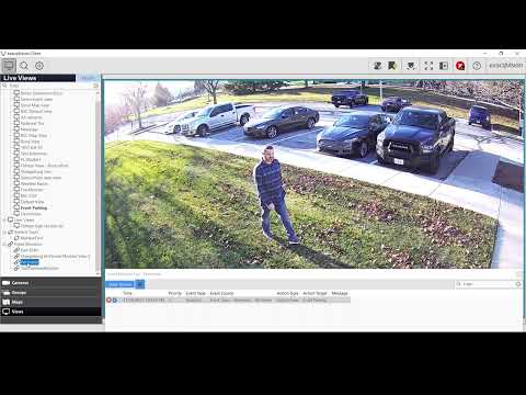
The Scenario Series of videos addresses setup configurations for specific use cases. In this video our scenario is that of a user that wants to use Event Monitoring to bring attention to an ExacqVision operator when a perimeter area is crossed. This could be used to monitor property and fence lines. We walk through setting up AI Object Classfication within an Illustra IQ camera and configuring Event Monitoring in ExacqVision to change our displayed camera views when triggered.
Categories
Knowledge Support Cloudvue Cloudvue Cameras Support Illustra Categories Products

Connecting an Analog Microphone to a Cloudvue C2C Camera

Cloudvue’s cloud-based recording solution provides the ability to record and playback audio. Many models of Illustra IQ cameras configured for Camera to Cloud (C2C) recording with Cloudvue’s services provide audio capabilities. Check your specific Illustra IQ camera model to determine audio support.

Considering audio quality, refer to manufacturer recommendations and guidelines on microphone selection and installation placement.

<br>

Camera Terminals

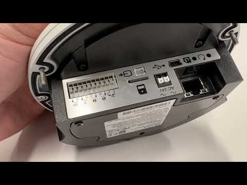
When examining your Illustra IQ camera, locate the I/O terminals. Determine which terminals are used for audio input. Examples from different models of Illustra IQ cameras are pictured below.

In this image, the icon with the triangle on the right is the positive terminal. The spaced lines on the left indicates ground.

<br><br>

Microphone Wiring

You will need a microphone with a pre-amplifier capable of producing a line level output that can be connected directly to the camera’s audio inputs.

If using a mic level output microphone, you will need a mic pre-amp to boost the audio to line level output for connection to the rear audio input terminals. Some microphones on the market have built-in pre-amps and others may require an external pre-amp.

There are many analog microphone options on the market. This article will focus on the Louroe Verifact A microphone used with an APR-1 single zone base station since it is a very commonly encountered device.

Looking at the back of a Louroe base station you will see that there are terminal inputs to connect your microphone to the base station and RCA style jacks for input and output.

The terminals on the microphone and base station are marked A, B, and C. Connect A on the mic to A on the base station, B to B, and C to C.

Since the audio output from the Louroe base station is an RCA jack and the camera does not have RCA audio inputs, you have two options. You may strip the wire end of a common RCA to RCA audio cable or purchase an RCA to bare wire cable. These may be found online and have already been striped and separated for you.

Connect the RCA connector to the audio output of the base station. With the bare end of the wire you’ll connect the conductor wire to the positive audio input terminal. In most cases this will be red. Connect the ground wire to the negative/ground audio input terminal, this will usually be black.

<br><br>

Preparing the Camera

Prior to changing the camera to Cloudvue Mode you will need to enable audio functions.

NOTE: Audio recording is restricted by law in many areas so this is disabled by default. Check the laws for audio monitoring and recording in your area prior to use since these can vary from video recording laws.

If your camera is already in Cloudvue Mode you will need to factory default it, then log into it as you would a standard IP camera using your web browser. Follow the camera manual’s steps for factory defaulting the device and accessing it within your web browser.

  1. Navigate to the Audio page, under the System menu.
  2. Check the box to Enable Audio.
  3. Select ‘External’ from the Input Source drop-down (only applicable on select models).
  4. Check that the Input Enable box is marked.
  5. Adjust the Input Volume level as needed.

After enabling audio, you will enable Cloudvue Mode.

  1. Navigate to the Maintenance page, under the System menu.
  2. Select the Cloudvue tab.
  3. Enter the Cloudvue Partner and Cloudvue Data Center as directed by your Cloudvue dealer before clicking the Apply button.

<br><br>

Cloudvue Audio Configuration

Follow the steps listed elsewhere for adding video devices to your Cloudvue account.

From your Cloudvue Settings page, select the Devices tab.

Beneath the C2C Settings section, click the Audio tab. This tab features a volume slider, which you may need to use to adjust for your installation. Note, the checkbox beside the Mute setting is disabled, stating it is in the ‘Off’ position. This is the default behavior and allows audio to be recorded. Checking the box, changing it to ‘On’, will mute all audio and nothing will be recorded or heard.

<br><br>

Audio Playback

The Archive search timeline in Cloudvue does not require that audio channels be selected and does not display audio on the timeline. When playing recorded video, the associated audio will automatically be played back with the corresponding video and is included with saved clips.

<br>

Categories
Knowledge Support Support Illustra Categories Products exacqVision Integrations

Clean Uninstall Illustra Body Worn Camera and Mobile Video Manager

Clean Uninstall Illustra Body Worn Camera and Mobile Video Manager

Introduction

This knowledge base article summarises how to cleanly remove the Illustra Body Worn Camera (BWC), JCI Dock Controller and the Illustra Mobile Video Manager software. 

Uninstall Body Worn Camera and JCI Dock Controller

  1. Uninstall JCI Dock controller software:
    Control Panel > Programs and Features > JCI Dock Controller > Uninstall
  2. Delete directory for JCI Dock Controller software:
    C:\windows\System32\config\systemprofile\AppData\Local\JCI Dock Controller
  3. Uninstall Body Worn Camera software:
    Control Panel > Programs and Features> Body Worn Camera > Uninstall
  4. Delete directory for BWC software:

C:\ProgramData\BWC

Uninstall Illustra Mobile Video Manager

  1. Uninstall the Illustra Mobile Video Manager application in Windows:
    Control Panel > Programs and Features> Illustra Mobile Video Manager > Uninstall
  2. Delete the Illustra Mobile Video Manager directory:
    C:\Program Files (x86)\Illustra Mobile Video Manager
  3. Delete the Registry key directory located at this path: Computer\HKEY_LOCAL_MACHINE\SOFTWARE\Wow6432Node\Illustra Mobile Video Manager

Tips

  1. The BWC setup.exe (Kiosk/JCI Dock Controller) must be installed prior to the Illustra Mobile Video Manager:

2. Usernames for the associated applications are noted below:
BWC Kiosk = “admin”
JCI Dock controller = “admin”
Illustra Mobile Video Manager = “Administrator”

Categories
Knowledge Support Support Illustra Categories

Illustra Body Worn Camera Installer – Dock Controller Section Fails.

Illustra Body Worn Camera Installer – Dock Controller Section Fails.

Introduction

This knowledge-based article provides a solution for a failure of the dock controller section of the Illustra Body Worn camera installation. 

This is due to an out-of-date cert on the MSI installer. The official release is due on the Illustra website in line with the exacq 23.03 release.

Solution

  1. Clean Uninstall Illustra Body Worn Camera and Mobile Video Manager using the following KB
    KB17494

2. Please provide the following installer to the customer which has an updated MSI for the dock controller.  

https://support.exacq.com/#/file-manager/6a69593a-fd48-43b4-950c-ed988ad2a815/kb17478

Categories
Video Library Configuration Demo Illustra exacqVision Client Youtube Video Library Categories Products

Scenario Series – Illustra IQ Object Classification to Change ExacqVision Views

<br>

The Scenario Series of videos addresses setup configurations for specific use cases.

In this video our scenario is that of a user that wants to use Event Monitoring to bring attention to an ExacqVision operator when someone parks in specific parking spaces. This could be used to prevent people from parking in forbidden areas, to alert someone to customers in curb-side pickup spots, and more.

We walk through setting up AI Object Classfication within an Illustra IQ camera and configuring Event Monitoring in ExacqVision to change our displayed camera views when triggered.

<br>

Categories
Knowledge Support Support Illustra exacqVision Server Categories Products

What is H.264 / H.265?

H.264 and H.265

H.264 (MPEG-4 AVC) and H.265 (MPEG-4 HEVC) are MPEG video standards. H.265 is the newer of these standards.<br><br>

What is Motion JPEG?

Motion JPEG is a compression format that is older than H.264/H.265 and was created as a version of the still image JPEG format for video use. It is often shortened to just JPEG in video applications.<br><br>

Why choose H.264/H.265 over Motion JPEG?

Motion JPEG ignores frame-to-frame data redundancy. When using Motion JPEG, each video frame is compressed using JPEG. The Motion JPEG video stream is then presented by displaying each frame in order.

H.264/H.265 improved upon this by using compression algorithms that compare frame-to-frame data to help eliminate the transmission of redundant data.

Both provide video compression far greater than Motion JPEG without sacrificing image quality.

Greater compression means big savings in terms of your network’s bandwidth consumption and the amount of space required to store recorded video on an NVR over Motion JPEG. Decreasing the amount of storage space needed will lead to longer retention times without increasing storage capacity. This aspect is even more important when considering use cases that require high numbers of cameras, high frame rates, and long retention times.

The following graph shows a comparison of three identical model 2MP cameras set to 15 frames per second, running the same firmware version. However, each camera is set to a different recording format. The camera set to Motion JPEG is shown at the top, in red. Below, the H.264 stream is shown in blue, and the H.265 stream just under that in green. The changes in data correspond with a person walking through the scene.

ExacqVision records files in 5 minute increments. Examining the files created from these 2MP cameras recording continuously for 5 minutes and then extrapolating their file sizes over the course of 24 hours, and 1 year, the amount of storage space saved is considerable.

5 minutes (KB)24 hours (GB)1 year (TB)
Motion JPEG705,453203.1774.2
H.26432,1329.253.4
H.26521,9666.32.3

<br><br>

How does H.264 work?

As mentioned Motion JPEG compresses each frame individually and all frames are essentially equal. H.264 and provides for multiple types of frames.

  • I-frames are somewhat similar to a Motion JPEG frame. An I-frame contains all the data needed and can be decoded without reference to any other frames. H.264 always begins with an I-frame, and you’ll learn why in a moment. These I-frames occur at regular intervals in the video. A camera’s GOV, or GOP, rate sets the distance between each I-frame.<br><br>
  • P-frames lie between the I-frames. P-frames reference the previous I-frames and are smaller because they only include the regions which have changed. This provides a huge benefit over Motion JPEG because you are not retransmitting data that hasn’t changed.

    Imagine a scene in which a building is in the background and a person enters the field of view. The camera is not moving, nor is the building, so the pixels making up the part of the image where the building stands do not need to be sent again. Instead, only those pixels representing the person that entered the scene are sent and these replace the pixels in the image displayed to you.<br><br>
  • B-frames are not provided by all applications or video devices. B-frames occur in between I-frames and P-frames, or between multiple P-frames. B-frames are predictive in nature. They refer not only to previous frames but to future frames as well. For this reason implementing B-frames is not always used in live video applications since there is a slight delay introduced due to the need to wait for additional frames to arrive before the B-frame can be created. When only I-frames and P-frames are used, it is referred to as an H.264 baseline stream.

H.264 compression is performed by processing and compressing the frames in regularly sized ‘macroblocks’ of 4 to 16 pixels, which are further broken down into smaller blocks for compression. The main takeaway is that the image frame is divided up in very regularly sizes areas.<br><br>

How does H.265 work?

H.265 includes the same types of frames as mentioned above, but it improves over H.264 by providing the ability to dynamically size the regions the frame is broken up into. Rather than the macroblocks, transform blocks, and prediction blocks of H.264, these dynamically sized areas are named Coding Tree Units (CTUs). This usually translates into more efficient compression than H.264 because the frame can be compressed more heavily in some areas than others when needed.

Illustrated below, H.264 on the left breaks up the image into equal blocks for compression. Whereas, on the right, H.265 divides the image into dynamically sized regions to better compress those regions based on what is in them.

An Illustration of H.264 (left) vs H.265 (right)

<br>