Categories
User Guides Documentation exacqVision Client Categories Products

exacqVision Start User Manual

exacqVision-Start-User-Manual-24.03.pdf
Categories
Video Library Configuration Demo exacqVision Server Youtube Video Library Categories Products

Exacq Scenario Series – Audio and Email Notifications After Business Hours

The Scenario Series of videos addresses setup configurations for specific use cases. In this video our scenario is that of a car dealership that wants to play an audible alert to people on the property after hours, as well as send a notification to staff members. We walk through setting up AI Object Classification on three different cameras from Illustra IQ, Axis, and Hanwha, then show how to configure Event Linking different ways and two different methods for scheduling the action to occur. Chapters 00:00 Intro & Review of Scenario 00:56 Axis C1310 Setup 02:32 Camera Configuration 02:59 Illustra 04:28 Axis 05:46 Hanwha 07:01 Event Linking 09:43 Notifications 10:46 Scheduling 14:16 Wrap-up
Categories
Documentation Integrations Categories Products exacqVision Integrations

Axis License Plate Verifier Serial Integration Guide

Overview

Axis offers a camera-based License Plate Verifier application for detecting and reading vehicle license plates. The data from the license plate captures may be viewed within the exacqVision Client as text, sent as serial over IP data. This document provides the steps to set up the integration with exacqVision.

NOTE: This guide is not meant to be a comprehensive guide for the Axis application itself. For greater details on licensing and configuration settings of the Axis License Plate Verifier, please refer to Axis support and documentation.

<br>

Requirements

Axis License Plate Verifier is currently supported on specific Axis camera models, using firmware 8.40 and higher. Visit Axis for a list of cameras compatible with this application.

<br>

Installing Axis License Plate Verifier

  1. Mount the camera at the best viewing angle for license plate reading. (See User Manual for more information)<br><br>
  2. Download the Axis License Plate Verifier application.<br><br>
  3. Login to the camera’s web interface and access the Settings page.<br><br>
  4. Depending on the camera firmware version, you may find the menu options along the bottom of the page or the side. Navigate to the Apps menu page.<br><br>
  5. Select the Add or Add App option.<br><br>
  6. Select the downloaded Axis License Plate Verifier application file.<br><br>
  7. After successful upload, the Axis License Plate Verifier application will be shown in the list of installed apps.

<br>

Licensing

The Axis License Plate Verifier application requires licensing from Axis, purchased separately. Please contact Axis for license orders.

When purchasing, you may be provided with a license code. This code must be used to generate a license key and may be done in one of two ways.

  • Use the Axis License Key Registration page, to enter the serial number and license code. Download the generated license key file.
  • Use the automatic key generation feature of the application. This requires that the camera have direct internet connectivity to communicate with Axis.

Firmware 11.x

  1. Select the vertical ellipses on the far-right side of the License Plate Verifier ribbon.
  2. Choose either:
    1. Activate with a license key to upload a key file
    2. Activate license automatically to download from Axis
      1. Enter the license code into the text field provided.
      2. Press the Activate button

Firmware 10.x

  1. Select the License Plate Verifier app
  2. Choose either:
    1. Use the center Install button to upload a key file
    2. Enter the license code into the text field provided, and press the Install button beside it

<br>

Configuring the Application

  1. Use the toggle switch to enable the application.
  2. Wait for the Status to indicate the application is Running. Shown below are the indicators for firmware 11.x and 10.x.

  3. Press the Open button to configure the application.
  4. If presented with a setup wizard, select Skip.

<br>

The main menu for the application displays tabs for various configuration settings, as follows:

Event log – displays live video from the camera as well as a searchable history of detected plates. Press the Live button to display live video and live updates to the log.

List management – provides the ability to add plate numbers to Allow and Block lists for access control purposes.

Settings – camera image, event, and access control settings.

Integration – configuration settings to send license plate information to external systems.

Refer to the Axis License Plate Verifier documentation for greater details on each setting and optimization for best performance. Each installation site is unique, but a general order of steps to follow will likely include:

  1. Select the Settings tab.<br><br>
  2. exacqVision integration will not utilize the settings within the Access control section. These settings affect utilization of relays or the camera’s I/O ports to communicate directly with access control devices or compatible access control software.<br><br>
  3. Within the Image panel, set the Resolution as needed.<br><br>
  4. The Save full frame setting only affects images saved to the camera’s local storage and does not affect the streaming video received by exacqVision.<br><br>
  5. Set the Region and Camera location based on the camera’s physical location to help optimize detection of plates expected to be read by the device.<br><br>
  6. Use the Edit area of interest button to adjust the area the camera will look for license plates. Keep the area as small as possible, while permitting room for vehicles of various sizes and alignment to the entry/exit path.<br><br>
  7. The Events section configures retention of events saved locally to the camera and does not affect the retention of data saved by exacqVision.<br><br>
  8. The Detection parameters section allows users to determine how strict the device will be with regard to matching plates listed in the Allow and Block lists.<br><br>IMPORTANT: License plate character recognition accuracy may vary based on angle to camera, lighting and weather conditions, plate size, etc. These may be important considerations when used for access control.<br><br>
  9. An Additional DataBETA is provided in License Plate Verifier versions 2.7.1 and higher to provide Country and Region of the plate. Enhancements in 2.9.19 and higher added Vehicle Type and Color. This data is included in the serial data regardless of being disabled and only controls the display of this data within Axis software.<br><br>
  10. Utilize the Event log tab to monitor how changes to settings affect the ability to consistently match the license plates seen.

<br>

Sending Data to exacqVision

After configuring the License Plate Verifier application for best results, you must configure the application to send data to the exacqVision Server.

  1. Within the License Plate Verifier application, select the Integration tab.<br><br>
  2. Within the Push event panel, you will configure an active profile.<br><br>
  3. Ensure the Protocol field is set to TCP.<br><br>
  4. The Server URL field will be set to the IP address of your exacqVision Server, followed by a port number of your choosing to communicate with exacqVision.
    Example: 192.168.0.25:9080<br>
    NOTE: You will enter this port number later when configuring your exacqVision Server to receive communications from the app, and must be a port number unused by other applications or devices communicating with the server.<br><br>
  5. You may choose to disregard the Device location settings if you’d like but the data entered here will be available in the data feed sent to exacqVision if you need to use it.<br><br>
  6. The Device ID field may be disregarded as well, but may be helpful if multiple devices are in use. This data will also be available in the data feed sent to exacqVision.<br><br>
  7. Under Event types, multiple options provide the ability to choose which data points are sent to exacqVision.
    New – first detection of a license plate
    Update – either a correction of a character on a previously detected license plate, or when a direction is detected as the plate moves and is tracked across the image.
    Lost – the last tracked event of the license plate before exiting the camera image, also contains the direction of the license plate.<br><br>
  8. Depending on the version of License Plate Verifier you are using, enable the Do not send images or Do not send images through HTTP POST toggle control.<br><br>
  9. Enable START to send event data to server.

<br>

exacqVision Serial Port Configuration

Configure the exacqVision Server software to receive the data sent from the License Plate Verifier app.

  1. Open the exacqVision Client software and select the Configuration button (cog wheel icon).<br><br>
  2. From the navigation tree along the left-hand side, expand the options shown beneath the name of the server.<br><br>
  3. Select Serial Ports from the tree.<br><br>
  4. Locate the IP connections panel and select the New button below it.<br><br>
  5. Enter a helpful name to identify the connection. This example has named this “AxisLPR”.<br><br>
  6. Select POS from the options in the Use column.<br><br>
  7. Skip to the Type column and select TCP Listener.<br><br>NOTE: The TCP Listener type may never show ‘Connected’ in the Status column. This is normal. A TCP Listener sits and waits for data to be received and will only ever show ‘Connected’ while receiving data. However, the incoming data is often so fast as to be imperceptible. In between each burst of data received it returns to a waiting state of ‘Disconnected’.<br><br>
  8. In the Address field, enter the IP address of the Axis camera you configured with the Axis License Plate Verifier in the steps above.<br><br>
  9. Use the Port field to enter the port number chosen in Step 4 of Sending Data to exacqVision above.<br><br>
  10. Change the Max Line Length field to ‘250’. Some of the data sent by the application is rather long, providing file paths to files locally stored on the camera. The Max Line Length forces a new line when the specified number of characters is met. Making this large enough to accommodate long lines will make your job setting Line Masks easier in a later step.<br><br>
  11. Return to the Profile column and select New. This will begin a new Serial Profile for you, configured in the next section. If you have a pre-existing profile for Axis License Plate Verifier, you may opt to select this instead.<br><br>
  12. Press Apply.

<br>

exacqVision Serial Profile Configuration

The Serial Profile configuration determines how the incoming data is displayed or recorded and provides additional options for events, if needed.

  1. Because New was selected from the Profile field in Serial Ports, a new profile is created automatically for you. Begin by changing the Name field to something descriptive for easy identification. The example shown has chosen to name this “AxisLPR”.<br>
    IMPORTANT: One of the most vital steps in getting Serial Profiles configured correctly is setting the SOT and EOT marker fields. These determine the beginning and end of each “transaction”. In the case of LPR these mark the start and end points of the data for each license plate detected by the camera.<br><br>
  2. When configuring the SOT and EOT markers it can be helpful to enable the Show Raw Data checkbox to view hidden formatting characters. At the time of publishing this guide we are using Axis License Plate Verifier version 2.3-1 through 2.10.13. The data points provided by the License Plate Verifier may change with versions, as noted previously in Configuring the Application, Step 9. Below is a sample of the raw data provided from a single plate read using version 2.10.13 of the app.
  1. Use the first line of the transaction to find a suitable SOT marker. In this case, the first line is
    {"packetCounter":"24947",\x0d\x0a.
    Watching the serial data, the packetCounter number changes with each transaction, so you should not use the entire line as the SOT. Instead enter just {"packetCounter" as the SOT to ensure that all transactions beginning with this string will be captured.<br><br>
  2. Now find a suitable EOT marker. Note how each line is terminated with \x0d\x0a, these are invisible formatting characters to perform a line feed and return. This would make a poor EOT marker as it would separate every line as a new transaction. However, the last data point works well, "sensorProviderID":"defaultID"\x0d\x0a. Adding this to the EOT marker field properly marks the end of the transaction.<br><br>NOTE: Using Steps 3 and 4 will help you to correctly bracket serial transactions of any type or adapt to any changes in formatting from different versions of Axis License Plate Verifier.<br><br>
  3. Leave the Parser and Marker Type fields as their default settings.<br><br>
  4. Press the Apply button to save your changes.<br><br>
  5. The Live Display tab allows you to view how the serial data overlay will appear on top of a live camera image or on an empty background and permits you to change the text formatting.

<br>

Line Masks

The Axis License Plate Verifier app sends several data points for each plate, some of which you may not wish to record or display to users of the exacqVision software. Line Masks hide all the text on any row with a matching string.

As an example, referring to the sample block of serial data in the previous section, one row begins with "imagesURI", listing the file path on the camera to the locally stored image. Most exacqVision users are unlikely to need this information. it may be hidden with the following steps.

  1. Within the Serial Profile, select the Line Masks tab.<br><br>
  2. Select the New button.<br><br>
  3. In the empty row that is added, enter the text in the String column. In this example, the text entered is "imagesURI".<br><br>
  4. The check boxes in the Live and Search columns for each text string determine where to apply the mask. If the box is checked for Live, the row will be hidden in Live view. If unchecked for Search, the row will still be displayed in serial search results. Checking both boxes will hide the row from both locations. In some cases it may be useful to hide data in Live, but leave it available in Search to perform forensic searches.<br><br>
  5. Press Apply to save your changes.<br><br>
  6. Repeat these steps as necessary for each line you wish to hide from Live or Search, using the Configuration or Live Display tabs to view your changes taking place.

<br>

String Replacements

In some cases you may find some text less human friendly. Selected text strings may be replaced to be more legible to users. Referring to the sample serial data block again, one of the data points provided is "plateRegion", which in the United States correlates with the State. This can be updated using the following steps:

  1. Within the Serial Profile, select the String Replacements tab.<br><br>
  2. Select the New button.<br><br>
  3. In the empty row that appears, enter the text to be replaced in the String column. In this example it is "plateRegion". Including or excluding the surrounding parenthesis is your choice.<br><br>
  4. In the Replace column, you will enter the text you wish to show instead. In this example is has been replaced with State.<br><br>
  5. Just as with Line Masks, each entry has the option of being applied to Live or Search as you choose.<br><br>
  6. Press Apply to save your changes.<br><br>
  7. Repeat as necessary for each string of text you wish to replace in Live or Search, using the Configuration or Live Display tabs to view your changes taking place.<br>

NOTE: Line Masks and String Replacements do not support wildcard characters or regex expressions at this time. This means that you cannot reformat types of data which are different in every transaction, such as the date and time parameters. They will appear in the format send from the License Plate Verifier application.

<br>

Event Keywords

Keywords may be configured within exacqVision Serial Profiles to trigger user configured actions when the selected keyword is detected in the serial data feed. Example actions include recording video on detection of plates on the Block list, or sending a notification when a specific vehicle’s plate arrives. This guide provides two such examples below, each of which will then be configured with Event Linking in the following section.<br><br>

Example 1

In this example, there is more than one Axis camera running License Plate Verifier sending data to the exacqVision Server. You want to perform an action when activity is detected by one of the cameras. In this example the steps will record video.

  1. Locate the "camera_info" field in the raw serial data, which contains the camera “SerialNumber” value. Make note of this value.
    <br><br>
  2. Within the Serial Profile, select the Event Keywords tab.<br><br>
  3. Select the New button.<br><br>
  4. In the empty row that appears, enter the serial number value into the String column, and ensure the Enable checkbox is marked.<br><br>
  5. Press the Apply button.<br><br>
  6. Continue to the Event Linking or Event Monitoring sections below, for Example 1.

<br>

Example 2

Newer versions of the License Plate Verifier provide the "plateList" data point, which can tell you if the plate is on the Allow or Block list. However, older versions did not provide this. The steps in this example will use a workaround for this on older versions, then use this in Event Linking to send a notification.

  1. Within the License Plate Verifier application, navigate to the List management page.<br><br>
  2. Add a license plate number of interest to either the Allow or Block list. Leave the Description field empty for now.
    <br><br>
  3. Return to the exacqVision Client and examine the raw serial data on the Serial Profiles page by checking the Show Raw Data checkbox.<br><br>
  4. Locate the data property for “plateListDescription” and note that the value is empty.
    <br><br>
  5. While the "plateListDescription" does not automatically contain any data, you can use the Description field to provide information for this or similar keyword uses.<br><br>
  6. Return to the camera app on the List management page. Select the Edit icon for the previously entered license plate from Step 2 above. In the image below we have entered Deny beside the entry in the Block list. Save your change.<br><br>
  7. Examine the raw data again in the exacqVision Serial Profile. The "plateListDescription" value will now display the description entered on the List management settings. You can now use this as an Event Keyword.
    <br><br>
  8. Navigate to the Event Keywords tab in the Serial Profile.<br><br>
  9. Select the New button.<br><br>
  10. In the empty row that appears, enter the description used in the app in Step 6 above. In the image below, we have entered Allow and Deny as separate keywords.
    <br><br>
  11. Select Apply.<br><br>
  12. Continue to the Event Linking section below, for Example 2.

<br>

Event Linking

The Event Linking page provides the capability to automate server-side actions triggered by a wide range of events. Refer to the exacqVision Client User Manual or our Video Library for further details on configuring Event Linking beyond these examples.

The examples below continue from the numbered examples in the Event Keywords section above.

Example 1

This example continues from Event Keywords – Example 1 above to record from one of several Axis LPR cameras connected to the same exacqVision NVR.

  1. Navigate to the Event Linking page within the exacqVision Client software.<br><br>
  2. Select the New button near the bottom of the page.<br><br>
  3. From the Event Type list, select Serial Profile.<br><br>
  4. The Event Source list will display all Serial Profiles followed by the configured keywords available. Select the profile you intend to use as a trigger. In this example, we selected “AxisLPR – Keyword B8A44F0ADBE2”, where the keyword is the serial number.<br><br>
  5. Select the Action Type from the next panel. In this example Record Video is selected.<br><br>
  6. From the Action Target list, you will select the target, which in this example is the camera to be recorded when the keyword is detected in the serial data.<br>
    NOTE: Notice that we did not use the term “seen in the serial data”. The keywords may still be detected within the raw serial data, even if hidden from view by Line Masks or String Replacements.<br><br>
  7. Press Apply to save your changes.

<br>

Example 2

This example continues from Event Keywords – Example 2 above with an example of sending a notification when a plate on the Block list is detected.

  1. Navigate to the Event Linking page within the exacqVision Client software.<br><br>
  2. Select the New button near the bottom of the page.<br><br>
  3. From the Event Type list, select Serial Profile.<br><br>
  4. The Event Source list will display all Serial Profiles followed by the configured keywords available. Select the profile you intend to use as a trigger. In this example, we selected “AxisLPR – Keyword Deny”, where Deny was previously entered as a keyword.<br><br>
  5. Select the Action Type from the next panel. In this example, we have selected Notify.<br><br>
  6. From the Action Target list, you will select the target, which in this example is a previously created Email Message Profile.
    NOTE: Sending a notification requires a successfully configured Email Server.<br><br>
  7. Press Apply to save your changes.

<br>

Event Monitoring

Event Monitoring will not be covered in detail in this guide, but provides the ability to trigger client-side actions such as changing views on events. Refer to the exacqVision Client User Manual or our Video Library for further details on configuring Event Monitoring.

Example 1

This example continues from Event Keywords – Example 1 above as an illustration of changing the view displayed to the user when any license plate is read by the License Plate Verifier app.

This example requires at least two previously saved Views. One will display multiple camera panels to be shown to the user when no other activity is present. The second contain only the video from the Axis camera running the License Plate Verifier with the serial number entered as an Event Keyword in previous steps.

  1. Navigate to the Event Monitoring page within the exacqVision Client software.<br><br>
  2. Select the New button to create a new Event Monitoring profile.<br><br>
  3. Enter a descriptive profile Name.<br><br>
  4. Select On Event from the Show Event List setting.<br><br>
  5. Check the Show Newest Event box.<br><br>
  6. Select the View button from the Type field.<br><br>
  7. Skip to the Event Type list near the bottom of the page and select Default.<br><br>
  8. The Default type has no source option. Skip to the the Action Type panel and select Switch View.<br><br>
  9. From the Action Target list, highlight the multi-camera view to be displayed when there is no activity.<br><br>
  10. Uncheck the Confirm checkbox near the bottom of the screen.
  1. Near the middle of the screen, under the Client Actions panel, press the New button.<br><br>
  2. From the Event Type list, select Serial Profile.<br><br>
  3. This example uses the serial number unique to the camera as the keyword to change Views. From the Event Source panel, locate the Serial Profile name followed by the camera’s serial number keyword and select it.<br><br>
  4. Leave the Lasts at Least box unchecked.<br><br>
  5. From the Action Type list, select Switch View.<br><br>
  6. Use the Action Target list to select the view to change to. In the image below, this is our single camera view showing the Axis License Plate Verifier camera.<br><br>
  7. If your Event Monitoring profile includes multiple view changes or LPR cameras, utilize the Priority setting to define which views take precedence.<br><br>
  8. If the Confirm box is left checked, the view will not return to the Default view until the exacqVision user confirms they’ve taken note of the event. If unchecked, the Timeout setting determines how many seconds must elapse before automatically returning to the Default view.<br><br>
  9. Press the Apply button at the bottom of the screen to save your changes.
  1. Navigate to the Live view of the exacqVision Client.<br><br>
  2. Activate the Event Monitoring profile by changing the left-hand navigation tree to Views. Scroll to the list of Event Monitors and drag the profile name to the live display panel. When data is received from the camera with that serial number, the view will automatically change to show that camera. Clearing events from the Event Monitor List that appears returns to the Default view.

<br>

Disable Client Indicator (optional)

Due to the nature of TCP Listeners only remaining periodically connected, as mentioned above in exacqVision Serial Port Configuration, Step 7, you may choose to disable the exacqVision Client Indicator message warning users of a loss in connection on the serial port.

  1. Select Indicators from the left-hand navigation tree.<br><br>
  2. If connected to multiple exacqVision Servers, select the system for which the Axis camera is sending license plate data.<br><br>
  3. Locate the line item under Error that reads, “Serial port {Source Name} not connected on system {System Name}”, and uncheck the Enabled box for this item.

<br>

Serial Live View

After careful application of several Line Masks and a couple of String Replacements, the Live view provides just the information desired for the user. In this case, the Date/Time, license plate number, and State. Recall that the text may be formatted on the Live Display tab of the Serial Profiles page.

  1. Navigate to Live view.<br><br>
  2. Change the device list shown to Cameras.<br><br>
  3. Find the name given to the Serial Port, then drag and drop it into a live camera panel to display serial data as it arrives. This can be done in an empty panel or as an overlay to live video.

<br>

Forensic Search

In the event you must search for a specific plate number, state, or other data, exacqVision provides the ability to search for serial data to expediate the process of locating events of interest.

  1. Navigate to the Search page<br><br>
  2. Checkmark the Serial Port providing the data you wish to search from the device tree on the left.<br><br>
  3. Select the device(s) you intend to search. You may include more than one camera, in the pictured example we have only selected one.<br><br>
  4. If you intend to search for specific terms in the serial data, enter this into the Search Serial text field provided. The drop-down allows you to select from previously used terms. This field is only provided when serial data devices are check marked for searching.<br><br>
  5. Enter the dates and times of your Search Range into the provided fields.<br><br>
  6. Press the Search button to populate the timeline with results.<br><br>
  7. If you wish to see the serial data recorded, toggle the Show/Hide Keywords and Serial Data button.<br><br>
  8. In the serial data explorer panel that appears note that the SOT and EOT markers configured in the Serial Profile affect the beginning and end of each transaction.<br><br>
  9. Clicking on any of the transactions listed will move the playhead on the timeline to that event.<br><br>
  10. Matches to serial data searched from Step 4 above, are highlighted.<br><br>
  11. Matches to serial data searched will also thin the results of the serial data events displayed on the timeline.

<br>

Troubleshooting

Serial data includes massive block of random characters

Cause: The “ImageArray” block appears within the serial data feed when the camera is sending image data through the HTTP POST method.

Solution: Return to the Integration settings page of the License Plate Verifier app. Enable the Do not send images or Do not send images through HTTP POST setting.

<br>

Product Links

<br>

Categories
Video Library Demo exacqVision Client Youtube Video Library Categories Products

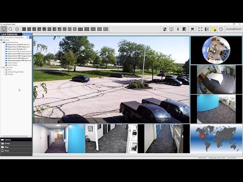
exacqVision Client Overview

Learn how to navigate the exacqVision Client software and get an introductory look at many of its features. Chapters 00:00 Intro 00:19 Three Client Modes 00:29 Live Viewing 01:03 Camera Associations 01:13 Mechanical & Digital PTZ 01:50 Fisheye/Dewarp 02:06 View Analytics 02:38 Search & exacqReplay 03:08 Search 03:34 Serial Search & Analytic Filters 03:59 Bookmarks & Cases 04:20 Configuration 05:55 Help Menu 06:27 User Training Videos
Categories
Knowledge Support Support exacqVision Client Categories Products

Missing Help Menu Options

Description

This article describes why some menu options may not appear to all users of the exacqVision Client software.

Products

  • exacqVision Client (all versions) – on Windows OS

Issue

  1. When pressing the Show Help button (?) in the upper-right corner of the exacqVision Client, some menu options are missing.
  2. When selecting Support Diagnostics from Show Help menu, the only button provided is Save.

Expected Results

Pressing the Show Help button provides many options, several of which link to useful pages on Exacq.com or the Exacq Support Portal.

Actual Results

  1. The Show Help menu provides only Help, Support Diagnostics, and About options.
  2. When exporting Support Diagnostics, the Upload button is not available to directly access and use the support web form page.

Solution

This is expected behavior when the exacqVision Client software is not run with administrator privileges. This is controlled by the operating system.

  1. To resolve temporarily, right-click on the exacqVision Client icon and choose Run as Administrator, or if performing from the Start menu Favorites, right-click the exacqVision Client icon, select More, then choose Run as Administrator.
  2. To resolve permanently, add the operating system user to the local OS Administrator group.

NOTE: Solutions listed above may not be possible if the IT policies at the site do not permit exacqVision Client workstation operators to have admin access.

<br>

Categories
Knowledge Support Support Categories Products exacqVision Integrations

Guidance on Using USB Network Interface Adapters

On occasion, Exacq Support is asked about using a USB network interface (NIC) on their system. This is more frequently asked by those with smaller units which may have only one network interface and a user is attempting to add additional network interfaces to span networks or attempt to increase network throughput by bonding/teaming multiple NICs.

Regardless of the system model or size, Exacq does not support or test USB NICs.

Exacq Support will also not recommend any specific NICs for this usage. Even NICs connected externally using USB 3.0 or USB-C may encounter issues, therefore Exacq only supports internally connected network interface cards and does not troubleshoot issues with third-party devices added by users.

<br>

Categories
Knowledge Support Support exacqVision Server Categories Products

exacqVision License Recovery

Description

An event, such as OS failure, requiring a reimage of your Exacq NVR may leave you with unlicensed exacqVision Server software. If you cannot locate a copy of the emailed license key from the time of purchase, or an exported copy of the .KEY file to use, what should you do?

<br>

Import from Exacq.com

Perhaps the simplest method is to follow the steps below.

  1. Provide an internet connection to the system.<br><br>
  2. Open the exacqVision Client.<br><br>
  3. Select the cog wheel icon in the upper-left to enter the Configuration screen.<br><br>
  4. From the navigation tree along the left side, locate the server name and expand this option.<br><br>
  5. Beneath the server name, select Configure System.<br><br>
  6. On the System tab, locate the License area. Press the Import button and select ‘From exacq.com‘.<br><br>
  7. This method will automatically import the most recent license from Exacq. Note, that if the license key is expired you may need to change your installed exacqVision Server version to one released prior to the license’s expiration date.

<br>

If the import fails or you are in need of other licensing information, contact Orders as directed below.

<br>

Contact Orders

Orders may be contacted by phone or email. Please be prepared to offer the system’s serial number or licensed MAC address.

+1-317-845-5710 select option 3 for Orders when prompted.

exacqorders@jci.com

<br>

Related Articles

<br>

Categories
User Guides Documentation Integrations exacqVision Client Categories Products exacqVision Integrations

Using the Axis TU9001 Control Board with exacqVision

This document will guide you through step-by-step procedures for keyboard use and suggested button mappings.

Product

  • Axis TU9001 Control Board
    • TU9002 Joystick
    • TU9003 Keypad

The Axis TU9001 Control Board consists of the combination of the TU9002 Joystick and the TU9003 Keypad.

IMPORTANT: The TU9002 and TU9003 appear to the operating system as separate devices. As of Client version 24.03 only one Joystick device may be enabled on a workstation at a time. This article will be updated in the case of further enhancements.

<br>

Setup

  1. Follow the Installation Guide from Axis for the steps to attach the two devices and connect the corresponding USB cables.<br><br>
  2. Plug the keyboard’s USB cable into the USB port on the Client viewing machine, where the keyboard will be operated from.<br><br>
  3. Navigate to the Joystick configuration page within the exacqVision Client.
    • Select the cog wheel icon in the top left-hand corner of the Client window to enter Configuration settings.
    • Expand Client from the navigation tree on the left-hand side.
    • Select Joystick from the tree to load the Joystick configuration page.<br><br>
  4. Select the joystick that appears from the drop-down menu. If the device fails to appear, close and re-open the exacqVision Client instance.
    <br><br>
  5. Select the Calibrate button to zero out the joystick positioning.<br><br>
  6. Adjust the sensitivity to your liking.
    • X/Y Axis controls camera Pan/Tilt, while Z Axis controls zoom.
    • Suggested settings include increasing the sensitivity on the X/Y Axis and Z Axis.

      <br><br>
  7. Pressing any of the buttons on the keyboard will highlight that number in the button menu to help you find the corresponding mapping. You may need to scroll the window if you do not see the button highlighted when pressed.
    <br><br>
  8. Once you have located the button, you may use the drop-down menu to select the action you wish to assign to the button.<br><br>
  9. After applying changes to the keyboard configuration, return to the Live camera view and the controls will be available for use.

<br>

Buttons on the TU9002 Joystick

The TU9002 features 7 buttons across the top of the device and 2 buttons on top of the joystick. The center Toggle button along the top acts as a Function Key. When pressed this will highlight button 17 in the button map, but you should notice the illuminated LEDs shift on the device. This toggles the ability to assign additional actions to each of the other buttons on the device.

For example, when the buttons are illuminated above, pressing J1 will highlight button 1 in exacqVision. If the center button is pressed, the illumination shifts below the buttons. Pressing the same button now highlights button 9 in exacqVision. The actions available in exacqVision Joystick settings do not align with the rewind, play/pause, forward symbols indicated on the device.

The TU9002 Joystick also features the ability to switch between joystick and mouse modes. The default mode is set to act as a joystick. Switch to mouse mode by pressing and holding the center Toggle button then press the J1 button. Moving the joystick now moves the mouse cursor. While in mouse mode the J1, J5, and left joystick button act as a left-click. The J2, J6, and right joystick button act as a right-click. Press and hold the Toggle button then press the J1 button again to revert back to joystick mode.<br><br>

    <br>

    Troubleshooting

    1. Check that the device is recognized by the operating system.
      • Windows – Navigate to Start > Control Panel > Game Controllers
      • Ubuntu/Linux – Open Terminal and run ‘lsusb’ to see if the devices are listed
    2. Check that the USB port is 2.0 or higher.
    3. Try alternate USB ports on the Client machine.
    4. Restart the exacqVision Client.
    5. Restart the Client worksation.

    <br>

    Categories
    User Guides Documentation Categories exacqVision Hardware Products

    X-Series Indicator Reference

    Power Supply Indicators

    LED IndicatorDescription
    Green (Solid)A valid power source is connected to the PSU and the PSU is operational.
    Amber (Blinking)Indicates an issue with the PSU.
    Not LitPower is not connected to the PSU.
    Green (Blinking)PSU firmware is being updated.

    WARNING: Do not disconnect power or unplug the PSU while firmware is updating. Interruption of this process could lead to PSUs ceasing to function.
    Green (Blinking and powers off)When hot-plugging a PSU, it will blink 5 times at a rate of 4Hz then power off. This indicates a mismatch due to efficiency, features, health status, or supported voltage.

    WARNING: If two PSUs are installed, both PSUs must have the same type of label. Mixing PSUs is not supported, even if they have the same power rating.

    WARNING: If two identical PSUs receive different input voltages, this can cause different output wattage and trigger a mismatch.

    CORRECTION: When correcting a PSU mismatch, remove all power from the system then replace the PSU with the blinking indicator.

    <br>

    System Health and ID Indicators

    The left control panel on the front of the system acts a button and provides an LED indicator. System ID mode, activated by pressing the control panel on the front of the system, or the ID button on the rear of the system will flash these LEDs to make identification in a server rack, from either side, easier.

    LED IndicatorDescription
    Blue (Solid)The system is powered on, healthy, and system ID mode is not active. Press the system ID button to switch to system ID mode.
    Blue (Blinking)System ID mode is active. Press the system ID button to switch to system health mode.
    Amber (Solid)The system is in fail-safe mode and should be inspected for issues or troubleshooting.
    Amber (Blinking)The system is experiencing a fault. Check the System Event Log for error messages.
    Look up specific error codes using Quick Resource Locator.

    <br>

    Drive Indicators

    The LEDs on the drive carrier indicate the state of each drive. Each drive carrier has two LEDs: an activity LED (green) and a status LED (bicolor green/amber). The activity LED blinks whenever the drive is accessed.

    1. Drive status LED indicator
    2. Drive activity LED indicator
    3. Drive capacity label
    LED IndicatorDescription
    Green (Solid)Indicates the drive is online.
    Green (Blinks twice per second)Indicates the drive is being identified, or preparing for removal.
    OffIndicates the drive is ready for removal.

    NOTE: Drive status indicator remains off until all drives are initialized after the system is powered on. Drives are not ready for removal during this period.
    Green/Amber (Blinks green, ambers, then powers off)Indicates that there is an unexpected drive failure.
    Amber (Blinking 4 times per second)Indicates the drive has failed.
    Green (Blinking slowly)Indicates the drive is rebuilding.
    Green/Amber (Blinks green 3 seconds, amber 3 seconds, then powers off after 6 seconds)Indicates that the rebuild has stopped.

    <br>

    iDRAC Direct (micro USB) Indicators

    LED IndicatorDescription
    Solid green for 2 secondsLaptop or tablet is connected.
    Blinking green (on for 2 seconds, off for 2 seconds)Laptop or tablet connected is recognized.
    LED offLaptop or tablet is unplugged.

    <br>

    Categories
    User Guides Documentation Integrations Categories exacqVision Hardware Products

    Using iDRAC on X-Series NVRs

    What is iDRAC?

    Integrated Dell Remote Access Controller (iDRAC) is a proprietary technology that allows IT administrators to remotely manage and monitor Dell-built servers. This includes software and hardware components.

    The Exacq X-Series NVRs include iDRAC micro ports on the front of the system and iDRAC network interfaces on the back. The location of these is noted on the X-Series Quick Start Guide.

    <br>

    Out of the Box

    iDRAC ports are not enabled out of the box. To enable either, or both interfaces, you must access the Lifecycle Control Center on the system.

    Enabling iDRAC Ports

    1. During boot up of the system, watch for the boot options to appear on screen.<br><br>
    2. When shown, press the F10 key to boot into the Lifecycle Control Center.
      <br><br>
    3. The Lifecycle Controller automatically begins a network configuration wizard if it has not been configured before. You may select the Back button to exit the wizard.<br><br>
    4. From the Lifecycle Controller Home screen, navigate to System Setup &gt; Advanced Hardware Configuration.
      <br><br>
    5. Select iDRAC Settings.

      Continue to Step 6 to enable iDRAC Direct on the iDRAC micro port. Skip to Step 7 to enable iDRAC networking.<br><br>
    6. To enable the iDRAC micro port, select Media and USB Port Settings.
      <br>
      • Beneath USB Management Port, locate the iDRAC Direct: USB Configuration XML setting.
      • The default setting is ‘Enabled while server has default credential settings only.’ However, for the security of your system, these credentials are changed before shipping from the factory.
      • Change the above-mentioned setting to ‘Enabled‘.
      • Select the Back button.<br><br>
    7. To enable the iDRAC network port on the rear of the system, select Network.


      NOTE: A VLAN is recommended as a best security practice when iDRAC is in Dedicated or Shared LOM mode, to isolate network access to iDRAC’s management interfaces. Technologies such as VLANs and firewalls help ensure that only authorized users can access network resources.<br><br>
      • Beneath Network Settings, change the Enabled NIC setting to ‘Enabled‘.
      • Leave the NIC Selection set to ‘Dedicated‘.
      • Scroll down to the IPv4 Settings section. The default settings are as follows:
        • Enable IPv4: Enabled
        • Enable DHCP: Enabled
        • Static IP Address: 0.0.0.0
        • Static Gateway: 0.0.0.0
        • Static Subnet Mask: 0.0.0.0
        • Use DHCP to obtain DNS server addresses: Disabled
        • Static Preferred DNS Server: 0.0.0.0
      • If you plan to connect this interface to a network with a DHCP server, you may leave the settings as they are.
      • If you wish to use a static IP address for the iDRAC interface, change the Enable DHCP setting to ‘Disabled‘ and enter the proper Static IP address settings in the fields below.
      • Select the Back button when done.
    8. Press the Finish button to save your changes and return to the System Setup menu.<br><br>
    9. Press Finish again to return to the Lifecycle Controller main menu.<br><br>
    10. Leave the Lifecycle Control Center and boot to the operating system by selecting the Exit option in the corner of the screen.

    <br>

    Accessing the iDRAC9 Dashboard

    The iDRAC9 Dashboard is accessible using any modern web browser, but there are various methods available to reach it: Local, Network, and USB (iDRAC Direct).
    <br>

    Local Browser Access

    Accessing the iDRAC9 Dashboard locally requires a keyboard, mouse, and monitor connected to the system.

    1. Log into the system’s operating system (Windows or Linux).<br><br>
    2. Open a web browser.<br><br>
    3. In the browser address bar, enter: https://169.254.1.1<br><br>
    4. Use the browser’s advanced settings to continue past the warning message. This message appears because the SSL certificate is self-signed.<br><br>
    5. Log into iDRAC using the proper credentials.

    <br>

    Network Access

    iDRAC network interfaces support RJ45 jacks, with 1G BASE-T Ethernet Cat5/6 cables.

    The Lifecycle Control Center provides the ability to set the iDRAC network interface to DHCP or static IP address.

    If set to a static IP address, a site administrator should be able to provide the configured address.

    If configured for DHCP, but a DHCP server is not available, or has no available addresses to offer, this interface should fall back to 192.168.0.120. Otherwise, you may need to determine what address the DHCP server assigned to the system.

    Whether using a static or dynamically allocated IP address, you will enter this address into the browser’s address bar.

    Example: https://172.10.10.4

    <br>

    USB Access (iDRAC Direct)

    iDRAC Direct allows you to utilize the front-facing iDRAC micro port to connect directly to the system over USB, say from a laptop, which makes ad hoc management in a server room/stack easily accessible.

    iDRAC micro ports couple with a USB 2.0 Micro-A or Micro-B connector. You will need a cable with either of these interfaces to connect between the X-Series system and your laptop/workstation. Cable length should not exceed 3ft (0.91m). Cable quality could affect performance. The iDRAC micro port is a Micro-A type port, which will accept either Micro-A or Micro-B connectors, but will not accept USB 3.0/SS Micro-B.

    1. Before beginning, you MUST disable all other network or wireless interfaces on the laptop/workstation you wish to connect from.<br><br>
    2. Make sure the iDRAC micro port is enabled, see Step 6 of Enabling iDRAC Ports above.<br><br>
    3. Turn the flat side of the USB micro connector to the right, so that the beveled side of the USB micro connector faces left, then insert the connector into the iDRAC micro port.<br><br>
    4. Wait a few moments and the laptop/workstation should detect a new virtual network interface.<br>
      This can be seen using the ipconfig command on Windows, or ifconfig command on Ubuntu/Linux.<br>
      The IP assigned to this interface should be 169.254.0.4.<br><br>
    5. Open a web browser on the laptop/workstation. In the browser address bar, enter the IP of the iDRAC micro port: https://169.254.0.3<br><br>
    6. Log into the iDRAC Dashboard with the proper credentials.

    <br>

    Logging into the iDRAC9 Dashboard

    When logging into the iDRAC9 Dashboard, use the following credentials

    Username: root

    Password: admin256

    Consider changing your iDRAC Dashboard password using the steps below.

    <br>

    Changing the iDRAC credentials

    Most system users will probably only use the default root user account and factory set password. However, up to 16 local users may be configured in iDRAC with specific access permissions.

    If you are already connected to the iDRAC9 Dashboard, you may do this using the following steps:

    1. Select the iDRAC Settings menu.<br><br>
    2. Select Users from the menu drop-down, or from the tabs on the iDRAC Settings page.

      <br><br>
    3. Select Local Users.
      <br><br>
    4. Edit an existing account or add a new user account.

    If you are not connected to the iDRAC9 Dashboard, you will need physical access to the system.

    1. During boot up of the system, watch for the boot options to appear on screen.<br><br>
    2. When shown, press the F10 key to boot into the Lifecycle Control Center.
      <br><br>
    3. The Lifecycle Control Center automatically begins a network configuration wizard if it has not been configured before. You may select the Back button to exit the wizard.<br><br>
    4. From the Lifecycle Controller Home screen, navigate to System Setup &gt; Advanced Hardware Configuration.
      <br><br>
    5. Select iDRAC Settings.
      <br><br>
    6. Scroll down to find and select User Configuration.
      <br><br>
    7. Select the text field beside Change Password to enter a new password.
      <br><br>
    8. When done, select the Back button.<br><br>
    9. Click the Finish button to save your changes.

    <br>

    iDRAC9 Dashboard Basics

    The iDRAC9 Dashboard provides a quick overview of the system. Describing all aspects and controls is outside the scope of this document. The items you should pay the most attention to are your system and drive health.

    The Dashboard home page shows a high-level overview of System Health and Drive Health.

    Clicking on Details for either of these will bring you to the corresponding pages. You may also reach these pages by selecting System or Storage from the top menu bar.

    The System &gt; Overview page displays the status of many hardware components, such as memory, CPU, power supplies, and cooling (system fans). Selecting any of these will provide greater detail on each.

    The Storage &gt; Overview page lists the number of physical disks, virtual disks, and graphics of drive status. 2U systems will also display a graphic of the system’s front panel to help identify the drive bays.

    Each Virtual Disk is comprised of multiple Physical Disks. These are listed on the corresponding Virtual Disks and Physical Disks pages.

    <br>

    Virtual Console

    iDRAC9 provides a Virtual Console feature which provides a desktop environment as if you were sitting in front of the system. This negates the need to also configure RDP or VNC to configure the system using a GUI.

    IMPORTANT: Do not use the Virtual Console for client monitoring of cameras. This method may be used to configure exacqVision software only: add and configure cameras, managing licensing, check system statuses and logs, etc. For regular camera monitoring, install the exacqVision Client on a client workstation suitable for this purpose. See system hardware requirements.

    NOTE: Virtual Console performs better when connected via the iDRAC network interface than when connected using iDRAC Direct using the micro USB port.

    Enabling the Virtual Console

    Virtual Console is disabled by default. Once logged into the iDRAC9 Dashboard, you may enable this feature for use.

    1. From the iDRAC9 Dashboard, locate the Virtual Console panel. The message in this panel indicates the feature is currently disabled for use.
      <br><br>
    2. Click on the Settings option above the empty panel.<br><br>
    3. From the Virtual Console settings page, change the Enabled setting from ‘Disabled’ to ‘Enabled’, then press the Apply button below.
      <br><br>
    4. Return to the Dashboard and note that the Virtual Console panel will display an image from the system based on its current state.<br><br>
    5. Select the inset image or press the Start the Virtual Console bar below to open a Virtual Console session.

    <br>

    Virtual Console Basics

    Virtual Console will open a session in a new browser window. Note that the frame rate of the console display is included in the window’s title bar. The console provides some of the following features from the menu buttons.
    <br><br>

    Menu ItemDescription
    BootChooses what the system will boot to on the next boot up. Options include the Lifecycle Controller, as well as physical or virtual media.
    PowerAllows the user to remotely power cycle or shutdown the system.
    ChatProvides a chat window for use when more than one person is using the machine’s Virtual Console.
    KeyboardDisplays a virtual keyboard. May be useful when attempting to enter multi-key commands such as CTRL+ALT+DEL.
    Screen CaptureAllows the user to save a screen capture PNG image to their local machine.
    RefreshRefreshes the console window.
    FullscreenDisplays the Virtual Console in fullscreen mode. Press ESC to exit fullscreen mode.
    Virtual MediaVirtual media allows the managed server to access media devices on the management station or ISO CD/DVD images on a network share as if they were devices on the managed server.

    Select Connect Virtual Media to begin, select your chosen media. Use Disconnect to remove that media from the machine’s console connection.
    Disconnect ViewerCloses the console session and window.
    Console ControlsProvides settings for viewing, including a virtual clipboard for copying text between the managed server and the management workstation.

    <br>

    Related articles

    X-Series Quick Start Guide

    X-Series Quick Start Video